3A59324G12
Description
1. Basic Information
2. Electrical Specifications
Input Design: Dual redundant power feed: cabinet auxiliary AC input + WESTBUS pre-regulated DC backplane dual feed-in
Rated Output: Triple regulated DC outputs: +5VDC, +12VDC, -12VDC; total continuous rated output power: 30W, consistent with G01/G02/G11 series
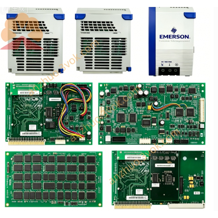
Multi-level Protection: Independent OVP (Over-Voltage Protection), OCP (Over-Current Protection), short-circuit latch-off and over-temperature auto-shutdown for each individual output channel
Front Panel Indication: Separate LED indicators for main power input, channel running status and overheat fault alarm
Ambient Rating: Operating temperature: 0℃ ~ +55℃; Storage temperature: -40℃ ~ +85℃; certified with UL safety standard and CE EMC industrial compliance
3. Core Functional Features
Dedicated power source for main control boards, communication modules and peripheral interface circuits installed inside MMI/OPR workstation rack.
Independent fault isolation design: only the defective channel cuts off power upon failure without triggering full workstation power outage.
Fault diagnostic data is uploaded to DPU controllers via WESTBUS field bus for system event logging and HMI screen fault alarming.
Supports hot-slot replacement: single module can be removed and replaced without full cabinet power interruption.
4. Upgrade Improvements vs G11 / G02 Versions
Full PCB conformal three-proof coating (moisture-proof, dust-proof, anti-corrosion), customized for high-humidity, corrosive on-site environment of thermal power and chemical plants.
Upgraded long-life high-temperature industrial electrolytic & hybrid solid capacitors to reduce component aging and bulging failure risks under continuous full-load operation.
Optimized input EMI filtering circuit to restrain grid surge noise and harmonic interference from cabinet power network.
Revised internal thermal layout for improved heat dissipation, lowering over-temperature protection activation rate during long-term 24/7 non-stop running.
5. Typical Application
6. Installation & Storage Guidelines
ESD anti-static protection is mandatory during plug/unplug operation; switch off corresponding slot power before module replacement.
Verify all three output voltages are within rated tolerance after power-on installation.
Spare modules shall be stored in constant-temperature anti-static warehouse; quarterly powered burn-in test is required to prevent capacitor degradation from long-term idle storage.
Conduct internal dust cleaning every six months for in-service modules to avoid heat accumulation and overheat protection trip.
Get a Quote