3174287-O
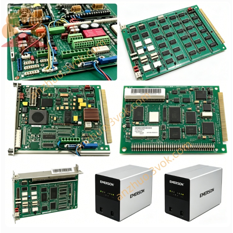
3174287-O is an output-type I/O module designed for Emerson Ovation distributed control system, matching the central controller 3169926C0 and series input modules such as 3174287-D for integrated cabinet installation and backplane bus communication. This module is responsible for receiving control commands transmitted from the main control unit and converting digital or analog control signals to drive on-site actuators including solenoid valves, regulating actuators and contactor equipment in thermal power, petrochemical and chemical process industries.
Description
The product adopts full channel isolation circuit design with built-in overcurrent, overvoltage and reverse wiring protection to resist transient surge and electromagnetic interference from complicated field working conditions. It supports standard discrete contact output and analog control output signals commonly used in industrial sites, conforms to standard DIN rail installation specification and supports hot plugging without cutting off the whole cabinet power during field maintenance to shorten equipment downtime. Equipped with onboard running status indicators and embedded self-diagnosis program, the module feeds real-time output channel state and fault information back to upper monitoring software through backplane bus. Its rated working ambient temperature ranges from 0 degree Celsius to 60 degree Celsius, adapting to conventional closed control cabinet environments with moderate dust and humidity in process industry production sites.
Part 2 English User Manual Content
Chapter 1 Safety Precautions
All installation, wiring, commissioning and maintenance work of 3174287-O must be performed by qualified certified automation technicians. Cut off both module internal control power and field load power before any wiring or disassembly work; live wiring is strictly prohibited to avoid electric shock and permanent damage to internal circuit components. Do not install the module in spaces with corrosive gas, continuous water splashing, heavy oil mist or ambient temperature beyond the rated working range. Prevent metal scraps and wire fragments from falling into module gaps during construction to avoid internal short circuit. Once abnormal overheating, burning odor or irregular indicator flashing appears during operation, cut off power supply immediately and stop running the module; repeated power-on tests are forbidden before fault elimination. For installation in hazardous explosion-proof areas, relevant local explosion-proof standards and matching safety accessory requirements must be followed strictly.
Chapter 2 Installation Instructions
Fix the module onto standard DIN rail inside closed control cabinet and lock the fixed buckle to prevent displacement caused by long-term equipment vibration. Separate high-power load output cables and low-voltage internal bus signal cables during wiring and keep proper spacing to reduce cross electromagnetic interference. Complete terminal wiring according to the terminal definition printed on module housing and tighten each terminal screw properly to avoid poor contact leading to intermittent output failure or channel loss. After wiring completion, clean excess wire residues around terminals and check all wiring connection status again. Insert the module vertically into matched cabinet backplane slot and push fully into position to ensure reliable contact between module golden finger and backplane bus terminals. Check cabinet internal ventilation condition to guarantee sufficient heat dissipation before initial power access.
Chapter 3 Power On and System Configuration
Finish all pre-installation inspections first, then switch on branch control power of the cabinet where the module is installed. The module automatically executes hardware self-test after power input; all panel indicators stay steadily lit if self-check passes, while abnormal blinking indicates bus connection failure or internal channel fault needing targeted inspection. Launch Ovation upper configuration software after normal startup, scan online devices via system bus function to identify mounted 3174287-O module, complete hardware address allocation and output channel function definition based on actual connected field load types. Set output range, action logic and protection threshold for each channel inside configuration software, verify all parameter settings and download configuration data into module internal memory. After successful download, switch corresponding control loop from offline debugging mode to online automatic running mode, test actual output action of on-site executing equipment to confirm normal command transmission from module to field devices. Regularly check real-time output state and historical operation records on upper monitoring screen during daily operation.
Chapter 4 Daily Maintenance and Storage Requirements
Carry out regular periodic maintenance for running modules. Remove dust on module shell and terminal area with dry soft brush; never use liquid cleaning agents to wipe circuit boards or terminals to prevent liquid infiltration induced short circuit. Check indicator status, terminal tightness and backplane insertion tightness in each maintenance cycle and retighten loose terminals in a timely manner. For unused spare modules, disconnect all external connecting cables and store in dry, ventilated normal temperature warehouse away from damp, corrosive gas and strong magnetic field. Perform regular power-on aging test every three months for long-term stored spare units to slow down electronic component aging. Back up module configuration data together with overall system regular backup to avoid data loss caused by unexpected hardware faults.
Chapter 5 Fault Troubleshooting Guide
If the whole module cannot power on after power supply is switched on, first check input control power voltage and corresponding branch fuse integrity, then inspect whether the module is fully inserted into backplane slot. When single output channel fails to drive field load normally, check on-site load circuit open or short fault first, then verify channel configuration parameters in upper computer software and inspect terminal wiring breakage. In case of communication loss between module and main control system, check backplane slot foreign matter obstruction and system address conflict, reset module address and rescan bus after removing external interference sources. Frequent abnormal channel alarms during operation require checking field actuator malfunction or module internal circuit damage by exporting historical alarm logs. If faults cannot be fixed through above self-inspection steps after software parameter reset and factory default restoration, contact Emerson official technical support for professional hardware repair service.
Get a Quote