3A59341G03
Description
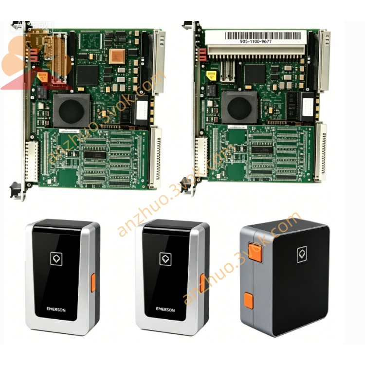
1. Product Overview
2. Electrical Specifications
Input Rating: Wide-range AC input from 85VAC to 264VAC directly fed from cabinet mains power.
DC Output: Stabilized +5VDC, +12VDC and -12VDC outputs with total rated continuous output power of 35W, dedicated to power VME backplane CPU boards, communication cards and memory modules inside workstation chassis.
Protection Features: Full-circuit overvoltage protection (OVP), overcurrent protection (OCP), short-circuit latch and thermal auto-shutdown; built-in EMI filter for surge and harmonic suppression on input side.
Environmental Parameters: Operating temperature ranges from 0℃ to +55℃ inside sealed control cabinet; storage temperature covers -40℃ to +85℃. The module complies with UL safety certification and CE industrial EMC standards.
Front Panel Indication: LED status lights for input power, output channel status and overheat fault indication.
3. Core Functional Features
Dual integrated functions: VME bus IIU interface together with built-in rack power feed, providing stable power for VME backplane while realizing data exchange between local VME hardware and system WESTBUS bus.
Collects fault signals from all VME slot modules, transmits diagnostic information to DPU main controller via system bus for event logging and HMI alarm popup on operator screen.
Independent fault isolation design: power section failure will not break the whole VME bus communication loop.
Standard VME Eurocard layout supports cold-swap replacement on single slot without complete workstation power shutdown.
4. Upgrade Improvements versus G01 & G02 Revisions
Full conformal three-proof coating applied on entire PCB for improved moisture, dust and corrosion resistance under high-humidity and dusty plant cabinet environments.
High-temperature long-service-life hybrid capacitors adopted to reduce aging and bulging failure rate under continuous full-load operation.
Optimized VME interface matching circuit to minimize data packet loss and abnormal communication errors caused by industrial electromagnetic interference.
5. Typical Application Scope
6. Installation and Maintenance Guidance
Strict ESD protection is required during module plug-in and removal; cut off corresponding slot power before replacement work.
Check all output voltages stay within rated tolerance after installation and power restoration, then perform full VME bus communication test.
Clean PCB surface and terminal contacts every six months for running equipment to avoid poor heat dissipation.
Store spare modules inside dry ESD-controlled warehouse and implement quarterly short-time powered aging test to prevent capacitor degradation caused by long-term idle storage.
Get a Quote