3174287-D
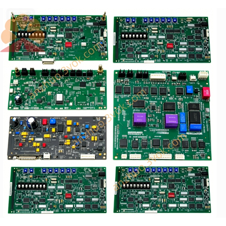
3174287-D is a dedicated signal processing input/output module belonging to Emerson Ovation distributed control system series, specially customized for thermal power, petrochemical and other process industrial automatic control systems, matched with the previously mentioned 3169926C0 central control module for cabinet-based combined installation and bus communication linkage. This unit serves as the intermediate signal conversion carrier between field site sensors, actuators and system main controller, responsible for collecting on-site analog and digital process signals, converting signal formats, transmitting processed data to main control unit, and outputting control instructions issued by upper controller to field terminal equipment.
Description
Adopting industrial anti-interference circuit design with built-in channel isolation protection circuit, the module supports standard 4-20mA analog signal, RTD thermal resistance temperature signal and dry contact discrete switching signal access, with built-in overvoltage, overcurrent and reverse connection protection functions to avoid instantaneous circuit surge damage under complex field power fluctuation conditions. Its compact industrial enclosure conforms to standard DIN rail installation specification, supporting hot swap replacement without cutting off the whole cabinet power supply during equipment maintenance, effectively shortening system downtime for on-site overhaul. The module integrates onboard status indicator circuit and hardware self-test logic, which can feed back real-time running state and channel fault information to upper computer control software via backplane bus, and features flexible address configuration to adapt to multi-point cascading layout of control cabinet. Applicable working ambient temperature ranges from 0°C to +60°C for continuous long-term operation, suitable for dusty, slightly humid conventional industrial control cabinet environment widely used in power plant boiler, turbine and chemical reactor automatic monitoring loops.
Part 2 Full English User Manual
Chapter 1 Safety Warnings
All installation, wiring, debugging and maintenance operations of 3174287-D shall be implemented by certified industrial automation maintenance technicians with relevant operation qualification. Cut off the corresponding cabinet branch power supply before disassembling module or modifying terminal wiring; live wiring is strictly forbidden to prevent electric shock accident and internal circuit burnout caused by wrong wiring. Do not mount the module in locations with strong corrosive gas, continuous water splashing, oil mist accumulation or ambient temperature exceeding rated working range. Prevent metal debris, wire scraps falling into module housing gap during cabinet wiring construction to avoid internal short-circuit fault. Immediately cut off power supply and stop usage once abnormal heating, peculiar burning smell or irregular indicator flicker appears during operation; prohibit repeated power-on test before troubleshooting root failure. For modules used in explosion-proof hazardous area, follow site explosion-proof specification and matched safety barrier wiring requirements strictly.
Chapter 2 Installation Guidance
Confirm cabinet DIN rail specification matches module fixed bayonet structure before installation, clamp module onto standard DIN rail steadily and lock fixed buckle to prevent falling off caused by equipment running vibration. Arrange strong-power power cables and weak-signal field split wiring separately during terminal wiring, keep certain spacing between two kinds of cables to reduce electromagnetic interference to low-level field signal transmission. Finish wiring in strict accordance with terminal definition sequence marked on module side housing, fasten each terminal screw moderately to avoid virtual connection resulting in intermittent signal loss or channel failure. After wiring completion, check all wiring connection status one by one, clear redundant wire ends inside terminal area. Insert module into cabinet backplane bus slot vertically and push in place to complete backplane communication docking; ensure no loose contact between module golden finger and backplane bus terminal. Complete cabinet ventilation inspection before power-on commissioning to guarantee cabinet internal heat dissipation meets continuous operation requirement.
Chapter 3 Power-on & System Configuration Steps
Complete all pre-installation inspection items specified in installation chapter firstly, then switch on branch power supply for the cabinet where 3174287-D locates. The module will automatically run built-in hardware self-check program after power input; all panel status indicators maintain stable normal status after successful self-test, abnormal blinking of indicator represents corresponding channel or bus connection fault needing targeted inspection. Open matched Ovation upper computer configuration software after normal startup, search online mounted module via system bus scanning function, complete hardware address binding and channel type definition according to actual on-site access signal type (analog input, digital input or output). Set signal range, engineering scale conversion parameter and alarm threshold for each independent channel in configuration interface, download finished configuration parameters into module internal storage chip after parameter verification. After configuration downloading completes, switch related control loop from offline debugging mode to online automatic control mode, observe real-time signal feedback value on upper monitoring screen to verify normal data transmission between module and field instruments.
Chapter 4 Routine Maintenance Specification
Implement periodic fixed-cycle inspection maintenance for on-service modules, clean surface accumulated dust of module housing and terminal area with dry soft brush; never use liquid cleaning solvent to wipe circuit board and terminal terminals directly to prevent liquid infiltration leading to circuit short damage. Check panel indicator working state, terminal wiring tightness and backplane insertion tightness during each regular maintenance; retighten loose terminal screws timely once found. For spare modules stored long-term out of cabinet, detach all external connecting wires and place in dry, ventilated room-temperature storage warehouse away from damp, corrosive gas and strong magnetic field environment. Conduct quarterly regular power-on aging test for long-term standby spare units to avoid internal component aging failure caused by long-term power-off standing. Back up module channel configuration data synchronously along with whole control system regular data backup cycle to prevent configuration loss from unexpected hardware damage.
Chapter 5 Fault Diagnosis & Troubleshooting
When the whole module cannot power on after cabinet power supply input, firstly check branch power voltage compliance with rated parameter and power circuit fuse integrity, then inspect module backplane bus insertion in-place status. In case of single channel no signal collection or abnormal data jump, check corresponding field instrument wiring breakage or short-circuit situation on-site, then verify channel parameter setting correctness in upper configuration software and replace damaged channel terminal if needed. If communication interruption occurs between module and upper control system, inspect backplane bus slot foreign matter blockage and system bus address conflict problem, re-scan and re-configure module address after eliminating interference source. When continuous channel alarm pops up during running, export system historical alarm log to confirm whether fault source comes from field equipment abnormality or module internal circuit damage; restore factory default parameter and reload backup configuration file after software configuration error confirmed. Contact Emerson official after-sales technical support for professional maintenance if internal hardware breakdown cannot be fixed via above self-inspection steps.
Get a Quote