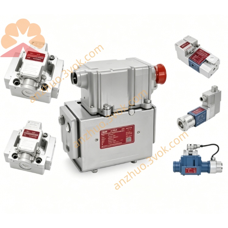
MOOG D663-344K Servo Valve
Description
Model Code Definition
D663 = Core series: ISO4401-05 NG10 installation dimension, ServoJet jet-pipe pilot stage, embedded drive circuit + full-range LVDT spool position closed-loop feedback
344 = Exclusive factory pre-calibrated trim number, fixed nominal flow parameter, locked amplifier gain and matched original pilot assembly
K = Electrical signal definition: factory preset 4~20mA DC analog current control input; standard NBR general-purpose sealing compatible with conventional mineral hydraulic oil
Technical Specifications
Hydraulic Parameters
Rated Flow:71 L/min @35bar single-side differential pressure; peak instantaneous flow 118 L/min @70bar supply differential pressure
Max Working Pressure:P/A/B main control ports up to 350bar; built-in T internal drain ≤50bar; standalone Y external drain supports full 350bar rated pressure
Full Stroke Step Response:≤23.5ms under standard 210bar supply oil pressure
Control Precision:Hysteresis<0.20%FS, Resolution<0.075%FS, overall thermal drift(-20~+78℃)<2.22%FS
Null Leakage:0.30~2.10 L/min, zero-overlap linear flow spool design
Working Medium:Anti-wear mineral hydraulic oil, fluid cleanliness NAS6~7 / ISO4406 17/14/11, operating fluid temperature -20℃~+80℃
Net Weight:3.08kg
Electrical Parameters
Input Power Supply:24VDC wide-range input(18~32VDC), static standby current ≤630mA
Standard Control Command:Factory fixed 4~20mA analog current input per K definition; ±10VDC voltage signal available via factory recalibration
EMC Compliance:EN55011 industrial EMC standard; standard 7-pin military circular connector with IP65 protection after complete cable assembly
Port & Connection Configuration
Hydraulic Interface:Standard ISO4401-05 NG10 hole layout with independent P supply port, A/B actuator control ports, internal T drain + separate external Y drain layout, standard cast valve body equipped with NBR full-port sealing
Electrical Interface:7-pin circular receptacle integrating power supply, 4~20mA control signal and full-stroke LVDT spool feedback signal; double-shielded control cable with single-point grounding at control cabinet; no digital fieldbus communication interface
Core Functions
1.Patented ServoJet jet-pipe pilot delivers superior anti-contamination capability versus traditional nozzle-flapper pilot, ensuring stable long-cycle continuous operation under moderately contaminated hydraulic medium。
2.Zero-lap main spool maintains ideal linear flow characteristic for seamless switching among position, speed and pressure three closed-loop control modes; built-in LVDT closed-loop dynamically compensates spool position drift induced by ambient temperature fluctuation.
3.Spring-centered fail-safe neutral structure:main spool automatically returns to center upon power loss to block A/B oil paths and lock hydraulic actuator for equipment overload protection.
4.K-configured 4~20mA input features strong anti-line-loss interference performance, suitable for long-distance field wiring in industrial workshop environments.
Typical Application
Metallurgical strip thickness closed-loop control, automotive hydraulic forming press servo system, universal material tensile/compression fatigue test bench, medium-size rubber injection molding precision core pulling control, hydraulic servo system for wind power component fatigue testing equipment.
Installation & Maintenance Instructions
1.Mount 3μm high-pressure precision inline filter on upstream supply pipeline; replace initial filter cartridge after 15 working days of commissioning startup.
2.Route power cable and shielded control wire inside separated wiring trough to avoid frequency converter harmonic interference on 4~20mA analog signal; fix valve with standard flat mounting washers during installation.
3.Flow gain and null offset are fully pre-calibrated at MOOG factory; only minor on-site potentiometer fine adjustment is permitted; complete disassembly of ServoJet pilot and main spool assembly is strictly prohibited.
4.Seal all unused hydraulic ports with original blank plugs for spare part storage; store in dry dustproof warehouse to prevent NBR seal ageing and hydraulic fluid leakage.
Get a Quote