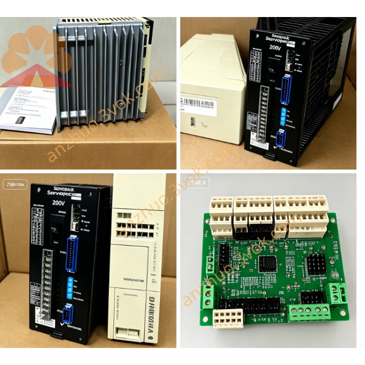
CACR-SR05SB1AFF
Description
1. MODEL CODE DEFINITION
CACR stands for Yaskawa classic Yasnac VS800 full digital AC SERVOPACK servo driver product series. SR means general-purpose servo unit supporting switchable position, speed and torque three control modes via internal parameter setting. 05 represents the matched rated motor power of 0.5 kilowatt specification. S refers to control mainboard S version hardware designed for incremental encoder matching circuit. B is power board revision B with standard internal power circuit layout. 1 indicates main input power specification of three-phase AC200V to 230V at 50Hz and 60Hz. The letter A denotes CN2 feedback interface configured exclusively for standard A/B/Z phase incremental encoder without absolute encoder supporting circuit. The first F means the drive prioritizes analog ±10VDC speed and torque command input as primary control signal. The second F stands for OEM customized fixed digital I/O definition and factory pre-set default parameters for dedicated equipment application. This model uses incremental encoder feedback and analog command as main control input, differing from absolute encoder and pulse command oriented variants.
2. TECHNICAL SPECIFICATIONS
2.1 Electrical Parameters
Main circuit power input is three-phase AC200V~230V with allowable voltage fluctuation range from minus 15 percent to plus 10 percent and compatible for 50Hz and 60Hz power supply frequency. Independent single-phase AC200V~230V terminals are reserved for separate control circuit power supply. Rated continuous output power reaches 0.5kW and rated continuous output current is 3.2A. The driver can bear 300 percent peak overload current of 9.6A within continuous 3 seconds and sustain 150 percent overload for up to 60 seconds. Rated DC bus working voltage ranges between DC280V and DC320V, and P/N terminals are reserved for external regenerative braking resistor connection under frequent high-load deceleration conditions.
2.2 Environmental and Mechanical Specifications
Permitted working ambient temperature is from 0 degree Celsius to plus 55 degree Celsius, short-time peak ambient temperature shall not exceed 60 degree Celsius, and storage transportation temperature covers minus 20 degree Celsius to plus 70 degree Celsius. Working relative humidity keeps between 5 percent and 80 percent without condensation. Ingress protection level is IP20 and the unit is only allowed to be installed inside sealed electrical control cabinet. Installation mode is vertical panel fixing, net weight is approximately 1.95 kilograms, maximum applicable installation altitude is limited within 1000 meters above sea level, and the driver can resist vibration of 10Hz to 55Hz with 0.5mm vibration amplitude.
2.3 Control Performance Index
The driver adopts IGBT sine wave PWM vector dual closed-loop control consisting of speed loop and position loop. Speed adjustment ratio can reach 1 to 5000 and steady-state speed control accuracy is controlled within ±0.01 percent under full rated load condition. Position control can also be realized via optional external differential pulse signal with maximum input pulse frequency up to 500kpps while analog signal remains the primary command source. Matching feedback device is standard differential incremental encoder with A/B/Z phase output only, multi-turn absolute encoder is not supported by internal hardware. Built-in digital notch filter function is available to suppress mechanical resonance and reduce equipment operating vibration.
2.4 Protection Functions
Complete built-in safety protection includes overcurrent protection, overvoltage protection, undervoltage protection, power input phase loss protection, drive overheat protection, motor overload protection, incremental encoder wire break protection, regenerative overvoltage protection and main CPU operation abnormal protection. All fault information can be displayed via front panel seven-segment digital tube with corresponding fault code.
3. INTERFACE AND COMMUNICATION CONFIGURATION
3.1 Main Power Terminals
R, S and T terminals are used for three-phase alternating current main power input; U, V and W terminals connect three-phase power line of matched servo motor; P and N spare terminals are used to connect external regenerative braking resistor for high-cycle frequent braking working condition.
3.2 Signal Connectors
CN1 is universal digital I/O terminal block equipped with 8 channels of opto-isolated digital input and 6 channels of relay isolated digital output, all signal logic definition follows fixed F-version OEM customized setting. Common configurable functions contain servo enable signal, forward and reverse travel limit signal, origin detection input, emergency stop input, servo ready output and fault alarm output. CN2 is dedicated encoder interface only for incremental A/B/Z phase encoder wiring and cannot connect absolute feedback encoder.
3.3 Command and Communication Interfaces
Primary control command comes from analog ±10VDC signal for speed or torque setting; external differential digital pulse serves as auxiliary alternative position command. Standard onboard RS422 serial port with exclusive Yaskawa proprietary communication protocol is used for parameter reading, writing and real-time operating status monitoring. Optional expansion accessory can realize Modbus-RTU bus communication to realize network connection with upper PLC control system.
4. CORE FUNCTIONS
First, three control modes including position, speed and torque can be freely switched by modifying internal parameters; electronic gear ratio parameter setting supports multi-axis synchronous linkage movement for automated production equipment. Second, automatic motor parameter identification function completes one-click measurement of motor resistance, inductance and rotor inertia data to automatically optimize closed-loop gain and shorten field debugging cycle. Third, internal integrated dynamic braking circuit absorbs most regenerative energy generated during motor deceleration, and external braking resistor is only required under heavy load and frequent emergency stop application. Fourth, segmented gain setting allows independent parameter configuration for low-speed and high-speed operation to guarantee stable low-speed running and fast dynamic response at high speed. Fifth, factory preset OEM parameters are pre-stored according to customized F specification; random parameter modification is not recommended unless original mechanical structure changes. Sixth, fault record storage function saves latest 10 groups of historical fault codes to facilitate subsequent maintenance and troubleshooting work.
5. APPLICABLE SCENARIOS
This servo driver is specially designed for low-power automation equipment taking analog voltage as main control signal, mainly applied to small-sized customized CNC auxiliary feed axis, automatic electronic component assembling equipment, small labeling conveyor system, miniature yarn feeding machinery and special customized automated testing fixture requiring incremental encoder positioning.
6. OPERATION AND ROUTINE MAINTENANCE INSTRUCTIONS
6.1 Pre-operation Check
Before switching on main power supply, carefully check all power cables, encoder wiring and I/O signal cables to eliminate hidden dangers such as short circuit, loose terminals and wrong wiring connection. Complete motor parameter matching and gain adjustment according to actual mechanical load; avoid arbitrary revision of factory preset customized parameters without mechanical modification.
6.2 Daily Operation Specification
Ensure the ventilation of installation electrical cabinet stays unobstructed, prohibit continuous long-time operation when internal cabinet temperature exceeds 55 degree Celsius, and avoid frequent repeated power-on and power-off within short time interval.
6.3 Periodic Maintenance
Conduct regular maintenance every three to six months: tighten all loose terminal screws, inspect cable outer insulation for aging and cracking condition, remove accumulated dust on driver heat sink and cabinet air duct. All internal disassembly maintenance operations must cut off total main power and wait at least 15 minutes for full discharge of internal DC bus capacitor to prevent electric shock accident. Once continuous fault alarm occurs during operation, cut off power immediately, inspect servo motor, connecting cables and mechanical stuck failure before restarting the whole equipment.
7. BASIC FAULT TROUBLESHOOTING
Overheat alarm usually results from blocked heat sink, overhigh cabinet ambient temperature or long-term continuous overload running. Encoder related fault alarm is generally caused by loose CN2 connector or broken incremental encoder connecting cable. Overvoltage fault mostly appears under frequent rapid deceleration with heavy load; install external regenerative braking resistor at P/N terminals to solve the problem.
Get a Quote