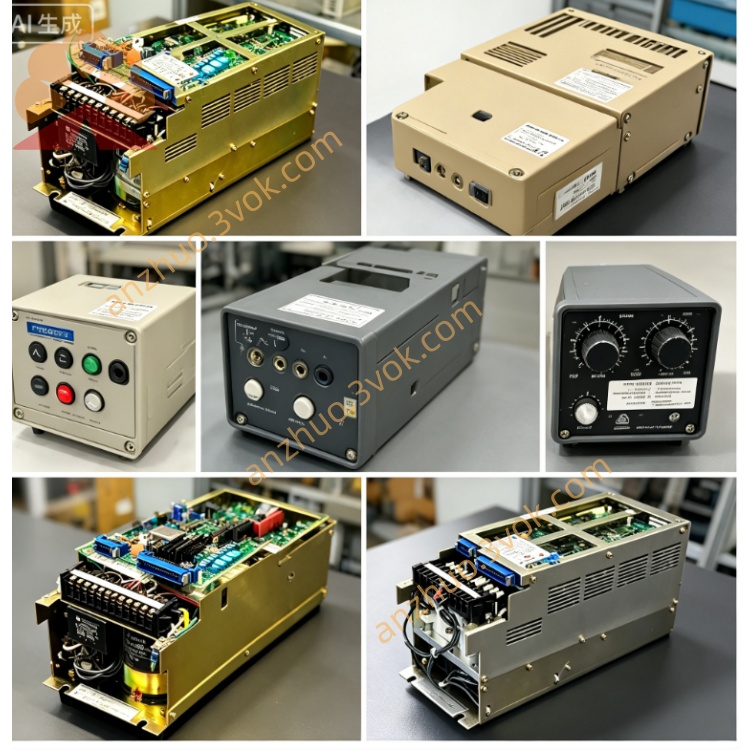
CACR-SR02AC1ER
CACR-SR02AC1ER is a discontinued analog SERVOPACK from Yaskawa, originally developed for Yasnac VS series CNC feed axis control. Its rated output power is 200W (0.2kW). Original mass production has been terminated globally, and only used or refurbished units are available for equipment maintenance replacement.
Description
1. Product Overview
CACR-SR02AC1ER is a discontinued analog SERVOPACK from Yaskawa, originally developed for Yasnac VS series CNC feed axis control. Its rated output power is 200W (0.2kW). Original mass production has been terminated globally, and only used or refurbished units are available for equipment maintenance replacement.
Model code breakdown:CACR-SR represents the classic analog servo drive platform for Yasnac CNC systems; 02 means 200W rated output capacity; A stands for standard control PCB configuration; C denotes AC200V single/three-phase input specification; 1 indicates differential line-driver pulse train position command input; E matches servomotors with 1500PPR incremental encoders; R refers to standard terminal layout and internal wiring design without factory OEM customization.
2. Electrical Specifications
Allowable input voltage ranges from AC180V to AC230V at 50/60Hz, compatible with single-phase or three-phase industrial power source. This amplifier is designed to pair with USAM-02 and USAF-02 200W Yaskawa servo motors equipped with 1500PPR incremental encoders. It adopts three-loop closed-loop control including current loop, speed loop and position loop, receiving position commands via differential pulse signals transmitted from Yasnac CNC main controller.
3. Environmental Specifications
The permitted operating ambient temperature is 0℃ to +60℃, and storage temperature ranges from -20℃ to +70℃. Working relative humidity must not exceed 80% without condensation, and the maximum installation altitude is limited to 1000 meters above sea level. The unit has IP20 protection rating and shall be installed inside electrical cabinets only.
4. Terminal and Connector Definition
R and S terminals are for main AC power input, while U, V and W terminals connect to three-phase servo motor windings. Extra terminals are reserved for external dynamic braking resistor connection when needed. CN1 is a 50-pin control connector for pulse command input, servo enable signal, servo ready output, fault alarm feedback and interlock signals with standard factory pin assignment. CN2 is a 20-pin exclusive connector dedicated to motor encoder wiring for position feedback signal transmission. All power terminals use screw-type fixed connection structure.
5. Power-on Operation and Parameter Setup
Complete wiring inspection and short-circuit check before energizing the drive. After power supply is switched on, the single-digit seven-segment LED on front panel shows normal standby status if no fault occurs. All default Cn group parameters are preset for standard 200W USAM/USAF series motors. Parameter modification should be completed by qualified maintenance staff only; improper setting may cause overload, motor stall or abnormal rotation. After parameter adjustment, cut off power for no less than three minutes to save modified data into internal memory chip. Front panel buttons support jog operation to test forward and reverse no-load motor rotation for abnormal noise or vibration inspection.
6. Protection Functions and Fault Diagnosis
Built-in protection functions cover overcurrent, overvoltage, undervoltage, continuous overload, overheat and encoder disconnection protection. The drive will shut down servo output instantly once any protection is triggered and display corresponding fault code on LED. Code 1 indicates overcurrent fault caused by motor short circuit or damaged power module; Code 2 stands for abnormal input voltage fluctuation; Code A means encoder open circuit failure; Code F refers to overheat due to clogged heat sink or defective cooling fan; Code C represents abnormal control circuit. After troubleshooting, cut power for more than 30 seconds to reset fault before restarting the equipment.
7. Maintenance and Replacement Guidance
Perform routine maintenance every three months including heat sink dust cleaning and terminal screw tightening, as well as regular cooling fan inspection. High residual high voltage stays inside internal main circuit capacitors after power-off; wait at least 10 minutes before disassembling the housing for internal maintenance. This standard non-customized model can be replaced with equivalent standard CACR-SR02AC1ER directly, but cannot be interchanged arbitrarily with Y-suffix customized versions without pin definition modification and parameter reset.
8. Application
It is originally used as feed axis servo amplifier for standard Yasnac VS-800 CNC lathes and small machining centers. Additional parameter calibration and wiring adjustment are required if applied to non-Yasnac CNC systems.
Get a Quote