MC-760VX
Description
1. Product Overview
2. Core Mechanical Specification
Axis Travel Range: X=760mm, Y=410~432mm, Z=485mm
Working Table: 1150mm × 410mm, maximum load capacity 500kg
Spindle: BT40 taper, rated 15HP motor, adjustable speed 1200~6000RPM max
ATC: 30-station arm-type automatic tool changer
Optional configuration: 4th-axis rotary indexing unit for complex multi-sided machining
3. CNC & Electrical Configuration (Yaskawa Yasnac MX Control)
Control system: YASNAC MX2 / MX3 closed-loop CNC controller, paired with Yaskawa CPCR-MR servo drivers
Control axis: Standard 3-axis linkage(X/Y/Z); expandable to 4-axis with optional rotary axis
Power input: Main AC200V 3-phase industrial power; control circuit DC24V for PCB and I/O modules
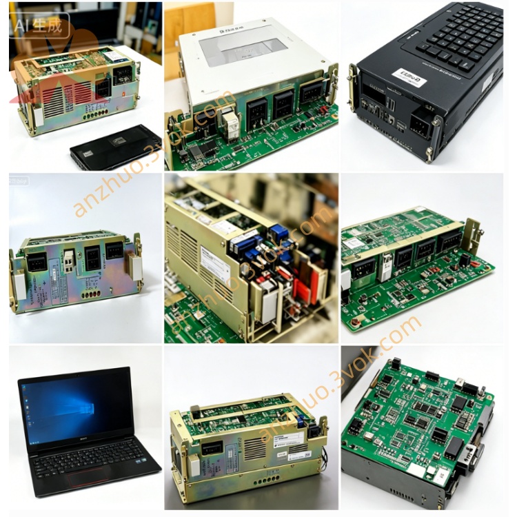
Internal control PCB lineup: Compatible with MORI-04 I/O safety board, MB20/MM20 main control board, Yaskawa servo axis board JZRCR-XSU02 / XC001B, matching LX-2 CNC operation panel
I/O layout: Built-in isolated digital input/output for coolant pump, spindle, door safety interlock, limit switch and fixture control
4. Environmental Requirement
Operating ambient temperature: 5℃ ~ 40℃ inside machine workshop; storage: -20℃ ~ +70℃
Humidity: 10%~85%RH non-condensation; isolate from cutting fluid mist, corrosive gas and heavy vibration
5. Standard PCB Replacement Procedure (For Yaskawa Control Boards)
Cut off total 3-phase AC main power of machine, wait over 15 minutes for servo drive capacitor full discharge before cabinet disassembly.
Mark all flat bus cables, DC24V wiring and field I/O cables connected on target PCB (MORI-04/XSU02 etc.) before unplugging connectors.
Remove fixed screws of faulty circuit board, install tested replacement board into original cabinet slot and lock fastening screws.
Restore all wiring strictly following pre-marked labels, double-check no short-circuit on power terminals.
Power on machine, complete CNC self-diagnosis, load original machine parameters, perform single-axis jog test and dry-run of automatic machining program.
6. Common Fault & Troubleshooting
CNC alarm 310/322 servo ready error, axes cannot move: Inspect damaged XSU02 servo board, loose flat cable or defective MB20 main control PCB.
Emergency stop / safety door interlock invalid: Check blown fuse or burnt relay on MORI-04 I/O board.
Axis positioning overshoot during cutting: Troubleshoot aging servo encoder cable or faulty XC001B axis drive board.
Spindle/ATC no response: Measure DC24V supply voltage and corresponding I/O channel circuit of control board.
Get a Quote