LX-2
Description
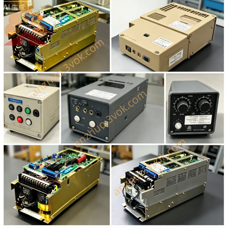
1. Product Overview
2. Core Electrical Specifications
Main input power: AC200V single-phase industrial power supply
Control circuit working voltage: DC24V for internal logic board & I/O modules
Axis control capacity: Standard configuration supports 2-axis (X/Z) closed-loop servo positioning; optional expansion for 3-axis linkage control
Servo interface: Dedicated signal terminals for connecting Yaskawa transistor-type PWM servo drivers, incremental encoder feedback input for position closed-loop control
Digital I/O: Built-in 32-point general-purpose input/output terminal, supporting spindle relay, coolant pump, door safety switch, travel limit signal access
Internal protective design: Overvoltage, overcurrent, power phase loss and servo fault detection with corresponding CNC alarm code display
3. Mechanical & Installation Details
Integrated panel-mounted structure, embedded installation on machine tool operation cabinet; overall control panel with display screen + membrane operation keypad
Main control unit dimension: approx W320 × H240 × D180mm; separate servo drive unit is DIN rail mounting inside electric cabinet
IP20 protection grade, natural convection cooling, only indoor enclosed cabinet installation allowed
4. Compatible Matching Components
Matched servo driver: CPCR-MR series Yaskawa PWM servo amplifier (core supporting part of LX2 system)
Supporting accessories: Yasnac dedicated spindle inverter, external I/O terminal block, original operation membrane panel, encoder cable set
Interchange note: Partial internal PCB can be cross-replaced with LX1 version after parameter modification
5. Operating Environmental Requirements
Continuous operating temperature: 0℃ ~ +45℃; storage ambient temperature: -20℃ ~ +70℃
Working humidity: 10%~85%RH non-condensation; avoid oil mist, cutting fluid vapor, corrosive gas and strong vibration near lathe processing area
6. Standard Replacement & Maintenance Steps
Cut off total AC input power of machine tool, wait 10+ minutes for servo drive capacitor full discharge before disassembly work.
Mark all power cables, servo signal lines and limit I/O wiring on LX2 control cabinet one by one then disconnect all connectors.
Remove fixing screws of old LX-2 controller, install replacement unit into original embedded position and fix tightly.
Restore all wiring strictly following pre-marked labels; confirm no short circuit of power terminals before power-on test.
Power on equipment, execute system initialization, set basic CNC parameters, perform single-axis jog test and automatic program trial run to verify no abnormal alarm.
7. Common Fault & Troubleshooting
CNC powers on with servo ready error, axes unable to move: Inspect DC24V control power or damaged connection between LX2 mainboard and CPCR-MR servo driver.
Axis overshoot / position deviation alarm during cutting: Check loose encoder wiring or aging internal servo feedback circuit of LX-2 control board.
Spindle or auxiliary I/O components no response: Measure input signal voltage of corresponding I/O terminal on LX-2 main control unit.
Get a Quote