JZRCR-XSU02
Description
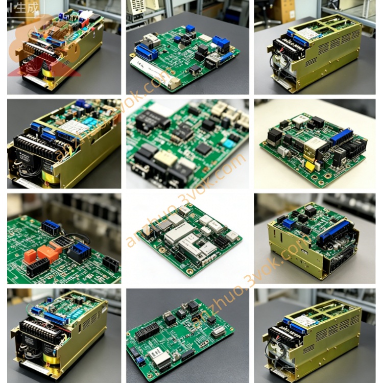
1. Product Overview
2. Electrical Specifications
Rated control input power: DC24V supplied by cabinet internal control power source
Built-in 4 standard SCSI communication ports for connecting each independent axis servo drive board; 2 groups of terminal blocks for digital I/O, brake control and fault signal transmission between cabinet backplane and peripheral circuit
Supports synchronous coordinated control of max 21 robot axes and dual-robot linkage operation; default onboard 48-point digital I/O, expandable to 144 I/O points via extension modules
Internal protection mechanism: overvoltage, overcurrent, overheat, encoder signal loss and position excess deviation protection with corresponding system alarm codes output
Natural air cooling design with side ventilation slots, IP20 protection grade for indoor cabinet installation only
3. Mechanical & Installation Details
Integrated galvanized anti-EMI metal casing to restrain servo high-frequency interference inside control cabinet; standard rack screw fixing structure for dedicated slot mounting in XRC cabinet, backplane plug-in wiring without extra cable modification
Overall dimension: approx W160 × H300 × D120mm, net weight about 2.8~3.5kg
Modular pluggable design enables direct one-to-one replacement of damaged unit without modifying cabinet wiring layout
4. Compatible Matching Parts
5. Working Environmental Requirements
Continuous operating temperature inside control cabinet: 0℃ ~ +55℃; storage ambient temperature after power cut: -20℃ ~ +70℃
Working relative humidity range: 10%~85%RH, non-condensation; installation location needs to avoid corrosive gas, oil mist, intense mechanical vibration and high-frequency electromagnetic interference from welding equipment and frequency converters
6. Standard Replacement Procedure
Cut off total AC input power of robot control cabinet, wait minimum 15 minutes to release residual high voltage inside power circuit for electric shock prevention before disassembly.
Mark all SCSI cables and terminal wiring connected on XSU02 sequentially, then disconnect all connectors one by one.
Remove fixing screws, take out faulty module and fix new replacement unit at original installation position tightly.
Reconnect all cables strictly following pre-marked wiring sequence.
Restore cabinet main power supply, finish system automatic self-inspection, execute single-axis jog operation to confirm no servo fault alarm and normal robot joint movement.
7. Common Fault & Troubleshooting
Whole robot system reports servo ready failure, all axes unable to jog: Inspect DC24V control power input or blown internal protection fuse on XSU02 mainboard.
Single axis constantly triggers position deviation/overload alarm: Check loose SCSI communication cable between XSU02 and corresponding XC001 servo board or damaged encoder signal channel inside the module.
Robot axes move abnormally with intermittent stop during automatic running: Clear accumulated dust blocking cooling vents causing overheat protection or check poor contact of terminal block I/O wiring.
Get a Quote