JZRCR-XC001B
Description
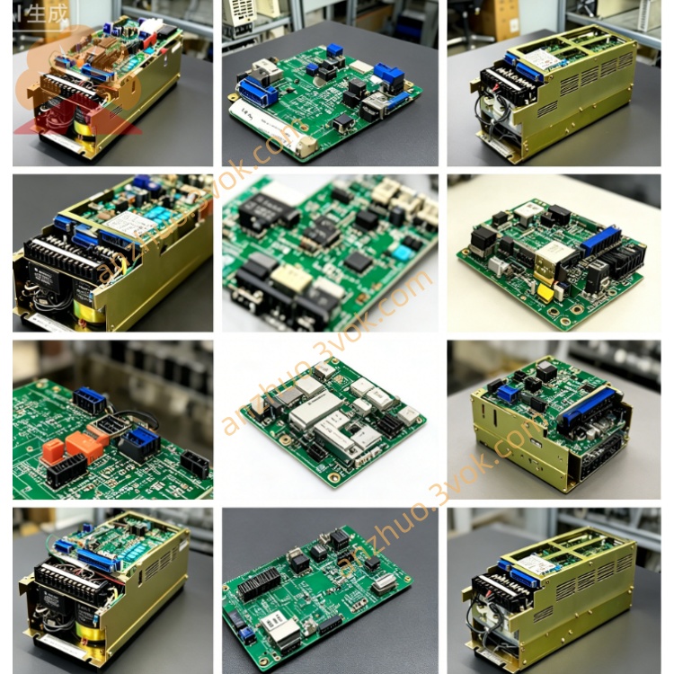
1. Product Overview
2. Core Electrical Specs
Control power input: DC24V supplied by cabinet internal control power module
Rated applicable motor power: standard 400W servo motor matching specification
Feedback interface: multi-channel encoder input ports for incremental/absolute motor encoder signal
Built-in protection: overcurrent, overvoltage, overheat, position deviation error protection with corresponding alarm code output
External I/O terminal: multi-row plug-in terminals for servo enable, brake control, fault signal output between drive and cabinet backplane
3. Mechanical & Installation Info
Full nickel-plated metal shield housing for anti-electromagnetic interference inside robot cabinet
Standard DIN rail & screw fixed structure, fixed at dedicated slot inside XRC control cabinet; direct plug-in with backplane wiring without extra wiring modification
Net weight: approx 1.31kg, natural convection cooling via side ventilation slits, IP20 indoor cabinet-only installation
4. Compatible Matching Parts
5. Ambient Operating Condition
Working ambient temperature inside cabinet: 0℃ ~ +50℃
Storage temperature: -20℃ ~ +70℃
Humidity: 10%~85% RH non-condensation; avoid oil mist, corrosive gas, strong vibration and welding high-frequency EMI environment
6. Replacement Operation Steps
Cut off robot cabinet total AC power and wait over 15 minutes to discharge residual high voltage inside the whole control system for electric shock prevention.
Mark all plug-in terminal cables on XC001B sequentially then disconnect all connectors.
Loosen fixing screws, remove faulty unit and install new replacement module in original position and fasten securely.
Reconnect all terminals strictly following previous marking.
Power on the cabinet, finish system self-check, jog single robot axes to verify no servo fault alarm and normal motor running.
7. Common Fault & Troubleshooting
Robot axes cannot jog with servo ready alarm: Check DC24V control input power or internal fuse blown on XC001B board.
Axis reports position deviation/overload alarm during operation: Inspect loose encoder wiring or damaged inner drive power circuit of the board.
Individual motor brake fails to release: Check brake control output channel and corresponding terminal connection on the unit.
Get a Quote