JZRCR-NTU04
JZRCR-NTU04 series is original Yaskawa Motoman NX100 robot cabinet integrated power supply unit, mainstream models include JZRCR-NTU04-2, JZRCR-NTU04C-3, JZRCR-NTU04E-3 variants, exclusively matched with NX100 controller system for HP, UP, VA, MA series six-axis industrial robots. This module is built-in switching power source plus auxiliary control circuit structure, responsible for converting cabinet input AC power into multi-channel stable DC working power for main CPU board, servo drive backplane, I/O circuit and teaching pendant of NX100 robot system. Original production has been discontinued by Yaskawa factory, available spare parts on market are brand new surplus or tested refurbished units for old NX100 robot maintenance replacement.
Description
1. Product Overview
JZRCR-NTU04 series is original Yaskawa Motoman NX100 robot cabinet integrated power supply unit, mainstream models include JZRCR-NTU04-2, JZRCR-NTU04C-3, JZRCR-NTU04E-3 variants, exclusively matched with NX100 controller system for HP, UP, VA, MA series six-axis industrial robots. This module is built-in switching power source plus auxiliary control circuit structure, responsible for converting cabinet input AC power into multi-channel stable DC working power for main CPU board, servo drive backplane, I/O circuit and teaching pendant of NX100 robot system. Original production has been discontinued by Yaskawa factory, available spare parts on market are brand new surplus or tested refurbished units for old NX100 robot maintenance replacement.
2. Electrical Parameters
Rated input specification is single-phase AC200V~230V, 50/60Hz, applicable input voltage fluctuation range ±10%. After internal rectification and high-frequency switching conversion, the module outputs multiple groups of regulated DC voltages including DC5V, DC24V and auxiliary low-voltage power to supply all core control boards inside NX100 cabinet. Built-in overvoltage, overcurrent, short-circuit and overheat protection circuit will automatically cut off output power once abnormal electrical condition occurs to avoid damage to downstream control components. Internal EMC filter circuit suppresses power grid surge and servo interference to stabilize system power supply quality.
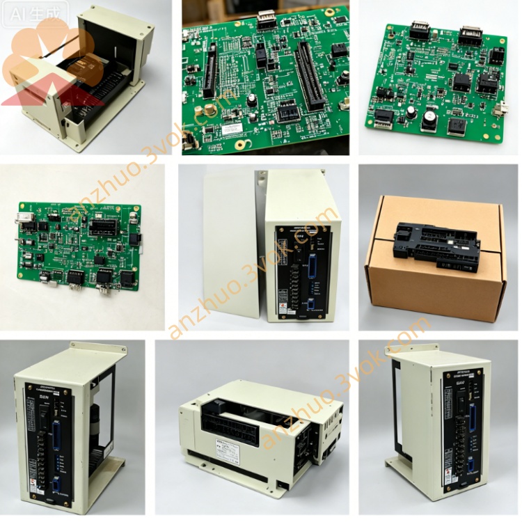
3. Mechanical & Installation Feature
Adopts closed metal shielding casing with internal PCB fixed by insulation bracket, whole unit is designed for standard embedded installation inside NX100 electrical cabinet fixed by mounting screws on cabinet internal rack. Multiple terminal connectors are reserved on side panel for AC input wiring and multi-channel DC output wiring to main backplane. The casing surface undergoes anti-rust electroplating treatment to adapt long-term dusty workshop cabinet environment, overall structure integrates heat dissipation slits for passive air cooling during continuous running.
4. Compatible Matching Parts
Perfectly matched with full set of NX100 system hardware including main control board JANCD-NCP01, servo backplane rack, each axis servo amplifier module and external teach pendant JZRCR-YPP21-1. It forms the whole robot power distribution core together with cabinet main contactor unit and emergency stop power loop components, all wiring follows NX100 original factory circuit definition standard for direct plug-and-play replacement.
5. Working Environment Condition
Allowable continuous operating temperature inside closed control cabinet is 0℃ ~ +55℃; storage temperature after power off ranges from -20℃ ~ +70℃. Working ambient relative humidity 10%~85% without dew condensation, installation location must stay away from oil mist, corrosive gas, strong vibration and high-frequency electromagnetic interference from welding equipment and high-power frequency converters, protection level IP20 only for indoor cabinet installation.
6. Replacement Operation Steps
Cut off total cabinet AC power supply and wait more than 15 minutes to discharge internal residual high voltage of power module to prevent electric shock hazard before disassembly. Mark all input and output wiring sequence of original NTU04 unit one by one then disconnect all connecting cables. Remove fixing bolts of faulty module and install new JZRCR-NTU04 unit on original fixed position firmly, recover all wiring strictly according to previous marks. After installation completion switch on main power and perform robot power-on self-check, confirm no power supply alarm and normal startup of teach pendant and each servo axis.
7. Common Fault & Troubleshooting
Fault 1: Robot no power-on, all panel indicators off after energization: Check AC200V input loop first, inspect internal fuse blow, rectifier circuit damage or open circuit of output power track inside NTU04 module.Fault 2: System randomly shutdown with intermittent low voltage alarm during running: Clean dust blocking heat dissipation slit causing overheat protection trigger, check loose terminal wiring leading to unstable power output.Fault 3: Teach pendant cannot power on while cabinet main board works normally: Inspect independent DC24V output channel circuit and corresponding output terminal damage of the power supply unit.
8. Safety Precautions
Hot unplugging input/output wiring under live power status is strictly forbidden; sudden power surge will break internal power circuit and peripheral control cards. All disassembly and maintenance work must be operated by professional technicians familiar with NX100 robot circuit principle. Do not arbitrarily modify internal component wiring of NTU04 module without official technical specification permission, unauthorized circuit change will lead to entire robot control system breakdown and operation safety risk.
Get a Quote