JZRCR-NTU01B
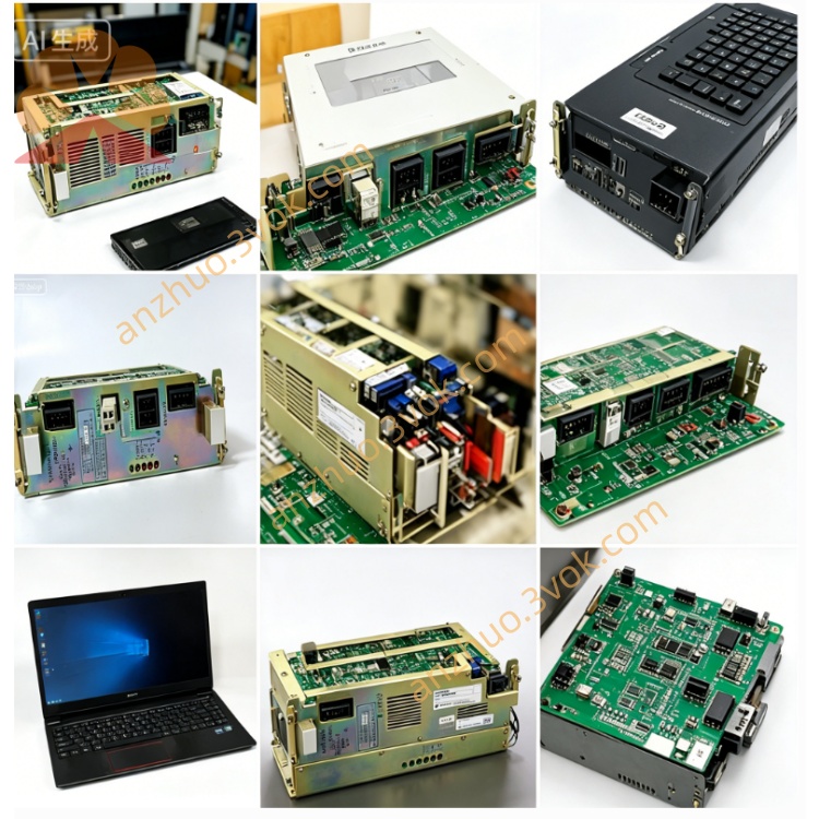
JZNC-XRK01B is original Yaskawa CPU backplane rack exclusively developed for MOTOMAN XRC series robot controller system, with common variant JZNC-XRK01B-1 for mainstream XRC cabinet matching. This empty rack without onboard control boards adopts integrated metal frame plus built-in backplane PCB structure, serving as installation base, power distribution carrier and internal system bus channel for core control modules inside XRC control cabinet. The product has been discontinued by Yaskawa original factory, and available supplies in market are mostly tested second-hand or refurbished spare parts for old robot maintenance. It is widely compatible with UP6, HP6, SK6, PX series and other classic XRC manipulator equipment.
Description
1. Product Overview
JZNC-XRK01B is original Yaskawa CPU backplane rack exclusively developed for MOTOMAN XRC series robot controller system, with common variant JZNC-XRK01B-1 for mainstream XRC cabinet matching. This empty rack without onboard control boards adopts integrated metal frame plus built-in backplane PCB structure, serving as installation base, power distribution carrier and internal system bus channel for core control modules inside XRC control cabinet. The product has been discontinued by Yaskawa original factory, and available supplies in market are mostly tested second-hand or refurbished spare parts for old robot maintenance. It is widely compatible with UP6, HP6, SK6, PX series and other classic XRC manipulator equipment.
2. Mechanical Specification
The rack is designed with three fixed plug-in slots inside the cavity, with fixed slot function layout. The left slot is dedicated for CPS-150F rack power supply module installation, middle slot is reserved for JANCD-XCP01 main CPU control board, and the right slot is configurable for optional memory expansion board or auxiliary I/O board according to robot practical configuration. Overall outer size is approximately 170mm in width, 190mm in depth and 300mm in height, net weight is about 2.6 kilograms. Multiple fixed wiring terminals are arranged at the rear panel for AC power input and signal external connection, and the shell surface adopts anti-rust galvanized treatment for long-term cabinet working environment protection.
3. Electrical Parameter
Rated input power specification is single-phase AC200V~230V, rated input current 2.1A with 50/60Hz applicable frequency. Alternating current is input from rear connector and transmitted to CPS-150F built-in power supply unit, which converts AC input into stable DC5V and DC24V working power. These two sets of direct current are distributed to all three slots via internal backplane printed circuit wiring to supply power for every plugged control board. The backplane integrates dedicated internal communication bus circuit to realize high-speed data transmission between main CPU, power module and expansion board, and built-in anti-interference filter circuit restricts electromagnetic interference generated by servo drive during robot operation.
4. Matching Standard Components
Standard matched accessories include CPS-150F control power supply, JANCD-XCP01 main system control board, optional JANCD-XMM01 memory expansion board and JANCD-XIF03 serial communication board. The assembled whole set forms core control unit of XRC robot controller, where main CPU board completes full robot motion control, interpolation operation, teach pendant signal interaction and servo system communication, and reserves RS232C serial port and PC card expansion interface for external program backup and data transmission.
5. Operating Environmental Requirements
Continuous allowable working ambient temperature inside closed control cabinet ranges from 0℃ to +55℃; storage ambient temperature after power cut is between -20℃ and +70℃. Working environment relative humidity keeps 10%~85% without condensation phenomenon. Installation position must avoid dense oil mist, corrosive gas, heavy dust, strong mechanical vibration and high-frequency electromagnetic interference from nearby welding equipment and high-power inverter devices. Protection grade of the whole rack is IP20, only applicable for indoor cabinet closed installation, cannot be directly used in open workshop with splashing liquid.
6. Installation & Replacement Operation Guide
Cut off total AC power supply of robot control cabinet before disassembly, keep power off for no less than 10 minutes to release residual high voltage inside built-in power module for electric shock prevention. Mark all external wiring positions and each plug-in card slot location before pulling out CPS-150F, CPU board and optional expansion boards sequentially from rack slots. Remove fixed mounting screws of original faulty rack and fix new JZNC-XRK01B rack on original installation position steadily. Install each functional card back to corresponding marked slots one by one and recover all external wiring following previous marking. Complete power-on self-test after installation, execute single-axis inching jog operation of robot to verify normal system communication and no alarm failure.
7. Common Fault Analysis & Troubleshooting
First fault: Cabinet cannot power on with all indicator lights off after energization. Check external AC200V input circuit first, then inspect open circuit, burned copper trace or damaged terminal pins on backplane PCB of the rack. Second fault: Random communication error alarm occurs during robot running with intermittent equipment shutdown. Pull out each plug-in board, clean oxidized golden finger contacts of circuit boards and slot inner contact terminals with industrial cleaning agent, inspect hidden poor solder joint on backplane circuit. Third fault: Partial function failure of expansion board only. Confirm the right slot backplane power supply circuit and bus wiring integrity, remove accumulated dust inside rack leading to short circuit or poor conduction.
8. Safety Warning Items
Hot plugging any circuit board or power module is strictly prohibited under powered status, instantaneous surge voltage will permanently damage backplane bus circuit and matched control modules. All disassembly, replacement and maintenance operations must be finished by professional maintenance technicians who have received systematic training on XRC robot control hardware. Do not modify internal backplane wiring structure of the rack arbitrarily without official technical specification permission; unauthorized circuit modification will cause whole system control breakdown and safety accident of manipulator.
Get a Quote