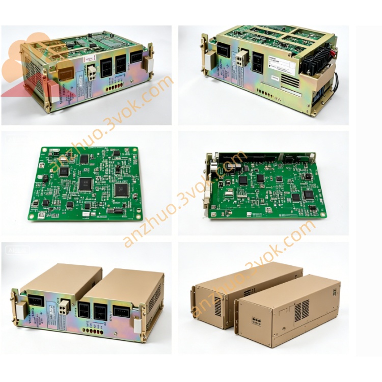
JZNC-TU07
JZNC-TU07 is an original plug-in switching power supply board made by Yaskawa Yasnac, designed exclusively for LX3 and MX3 legacy CNC systems. This power card plugs directly into the slots of JZNC-RK41 and JZNC-RK42 backplane racks, serving as the main power source for the whole control unit including JZNC-RK32 main CPU board, servo control boards, I/O interface boards and JZNC-OP15, JZNC-OP16 operator panels. No separate standalone English manual is released for this component, and all technical information is extracted from official Yasnac LX3 and MX3 hardware maintenance documents.
Description
1. General Description
JZNC-TU07 is an original plug-in switching power supply board made by Yaskawa Yasnac, designed exclusively for LX3 and MX3 legacy CNC systems. This power card plugs directly into the slots of JZNC-RK41 and JZNC-RK42 backplane racks, serving as the main power source for the whole control unit including JZNC-RK32 main CPU board, servo control boards, I/O interface boards and JZNC-OP15, JZNC-OP16 operator panels. No separate standalone English manual is released for this component, and all technical information is extracted from official Yasnac LX3 and MX3 hardware maintenance documents.
2. Electrical Specifications
The board accepts single-phase AC200V ±10% input power from machine cabinet power source with standard 50Hz or 60Hz frequency. It converts alternating current into multiple regulated direct current outputs to feed different internal circuits of the CNC system. It provides DC24V output for system bus and peripheral signal circuits, plus ±5V and ±12V auxiliary power for CPU logic circuit and encoder signal processing circuits. Total rated power consumption under full load is around 10 watts. Built-in fuse and overvoltage, overcurrent and short-circuit protection circuits are integrated on PCB; the power supply will lock off all outputs automatically once overload or short fault occurs to prevent cascaded damage of other plugged circuit boards.
3. Main Functions
This unit converts AC input into multi-channel stable DC power and distributes power to every functional card mounted on RK41 or RK42 backplane rack. Onboard filter circuits suppress high-frequency electromagnetic interference generated by servo drive startup and shutdown to keep system bus voltage steady during machine operation. Its self-protection function cuts off all DC outputs instantly under abnormal electrical conditions to avoid permanent burnout of main CPU, servo boards and peripheral I/O modules.
4. Compatible Components
This power board matches JZNC-RK32 series main control CPU board, JZNC-RK41 and JZNC-RK42 backplane chassis, MMI3 and MMI4 servo axis control boards, CPI1 series I/O expansion boards as well as JZNC-OP15 and JZNC-OP16 front operator panels for Yasnac LX3 and MX3 CNC equipment.
5. Environmental Working Conditions
Continuous operating ambient temperature ranges from zero degree Celsius to fifty-five degree Celsius inside sealed control cabinet, while permissible storage temperature after power shutdown is from minus twenty degree Celsius to seventy degree Celsius. Working ambient relative humidity should maintain between ten percent and eighty-five percent without condensation of water vapor. Installation location must avoid oil mist, corrosive gas, heavy dust, intense mechanical vibration and strong electromagnetic field from welding or high-power inverter equipment.
6. Installation and Replacement Procedure
Cut off total AC power supply of the entire machine completely and wait more than ten minutes for residual voltage release of internal large capacitors before any disassembly work to avoid electric shock risk. Mark the original slot position of JZNC-TU07 on backplane rack, then pull out the faulty power board straight from its installation slot. Insert new replacement TU07 into the corresponding vacant slot and ensure full contact between board edge gold finger and backplane pins. After finishing installation, switch on main cabinet power and check all system indicator lamps and operator panel display status to confirm normal power output before machine trial operation.
7. Common Troubleshooting Guidance
No indicator lights turn on and operator panel stays completely dark after power-on: check AC200V input supply condition and verify if onboard input fuse is blown or internal rectifier circuit is damaged. System randomly restarts or generates power abnormality alarm during running: inspect aging and bulging electrolytic capacitors on PCB which usually lead to insufficient output voltage of 5V or 24V channels. Single functional card works abnormally while other system parts run normally: troubleshoot failure of corresponding independent auxiliary power channel on TU07 board.
8. Safety Precautions
Internal circuit of TU07 contains high voltage area even after equipment power is disconnected, unauthorized disassembly of sealed power components is forbidden. All maintenance and replacement work should be carried out by professional technicians familiar with Yasnac LX3 and MX3 system structure. Original factory production of JZNC-TU07 has been discontinued, and available spare parts on market are mostly used or refurbished units for old machine maintenance only.
JZNC-TU07
JZNC-TU07 English Manual Content (No picture, no table)
1. General Description
JZNC-TU07 is a rack plug-in power supply board manufactured by Yaskawa Yasnac for LX3 and MX3 CNC control systems. It is designed to be installed on JZNC-RK41 or JZNC-RK42 backplane rack and supplies all working voltages for the whole control system including main CPU board JZNC-RK32, servo control boards, I/O modules and OP15, OP16 operator panels. No separate official single manual is issued for this board, all specification information is collected from original Yasnac system maintenance files.
2. Electrical Specification
The board receives single phase AC200V plus or minus ten percent input power at 50 or 60 hertz from machine cabinet power source. It converts alternating current into several groups of stabilized direct current outputs. DC24V is provided for system bus and external signal circuits, plus minus five volt and plus minus twelve volt serve CPU logic circuits and encoder related circuits respectively. The total rated power is around ten watts under full load operation. An internal fuse and integrated overvoltage, overcurrent and short-circuit protection circuits are equipped on the printed circuit board. The power unit will shut down all outputs automatically once abnormal overload or short-circuit happens so as to protect other plug-in boards from damage caused by abnormal voltage.
3. Main Function
This power card converts input AC voltage into multiple stable DC power and distributes power to all functional boards mounted on backplane rack. Built-in filter components restrain high frequency interference produced when servo drivers start or stop, maintaining stable bus voltage during machine running. Its built-in protection circuit can cut off all output immediately under electrical faults to prevent permanent burnout of CPU, servo boards and peripheral I/O modules.
4. Compatible Parts
This power supply board works together with JZNC-RK32 main control board, JZNC-RK41 and JZNC-RK42 backplane chassis, MMI3 and MMI4 servo axis boards, CPI1 series I/O boards as well as JZNC-OP15 and JZNC-OP16 operation panels which belong to LX3 and MX3 CNC series.
5. Ambient Condition
The allowable continuous working temperature ranges from zero degree Celsius to fifty-five degree Celsius inside closed electrical cabinet, and storage temperature after power off is between minus twenty degree Celsius and seventy degree Celsius. Working relative humidity keeps from ten percent to eighty-five percent without dew condensation. The installation position must stay away from oil mist, corrosive gas, heavy dust, strong vibration and intensive electromagnetic interference from welding equipment or high power inverters.
6. Replacement Instruction
Cut off total machine main AC power completely and wait at least ten minutes for internal capacitor residual voltage discharging to avoid electric shock risk. Confirm the original slot position of TU07 then pull out the faulty board from rack slot smoothly. Insert new replacement board into the original slot and make sure gold finger connects tightly with backplane pins. After installation finished, switch on cabinet power and check panel display and system indicator status to confirm normal power supply before machine test run.
7. Common Troubleshooting
All indicators off and operator panel keeps dark after power on, check AC200V input voltage and inspect blown input fuse or damaged rectifier circuit on the board. System unexpected restart or power fault alarm appears frequently during operation, check aging bulging electrolytic capacitors which cause insufficient output voltage of five volt or twenty-four volt. Only single plug-in board works abnormally while other parts run normally, check corresponding auxiliary power channel failure on TU07.
8. Safety Reminder
High voltage still remains inside power circuit long after power shutdown, unauthorized disassembly of internal power components is prohibited. All maintenance work should be finished by trained technicians familiar with Yasnac LX3 and MX3 hardware structure. Original production of JZNC-TU07 has been stopped, available spare parts in market are mostly second-hand or refurbished items for old equipment maintenance.
Get a Quote