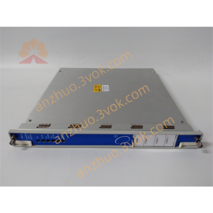
3500/34 4-Channel Relay Module (Bently Nevada)
Description
Model Interpretation
3500/34
3500/34: Base model (4‑channel TMR relay module)
Part Numbers: 125696‑01, 125712‑01 (common variants)
Designation: TMR = Triple Modular Redundancy; each output channel uses 3 internal relays with 2/3 voting.
Technical Parameters
Mechanical
Form Factor: Full‑height, single‑slot
Dimensions (H×W×D): 241 mm × 24.4 mm × 242 mm
Weight: ~0.91 kg
Installation: Full‑height slot in 3500/05 rack (TMR system only)
Relay Channels (4 Channels, TMR)
Output Channels: 4 independent external relay channels
Internal Redundancy: 3 DPDT relays per channel (2/3 voting)
Contact Type: DPDT (configurable as SPST externally)
Contact Rating: 5 A @ 250 VAC / 125 VDC (resistive)
Isolation: 2500 VAC between coil and contacts
Response Time: <25 ms
Logic: AND/OR programmable; maps to any monitor channel’s Alert/Danger
Power & Environmental
Power Consumption: ~9.6 W (from rack backplane, −24 VDC)
Operating Temp: −30°C to +65°C
Storage Temp: −40°C to +85°C
Humidity: 5%–95% RH, non‑condensing
Status LEDs: OK, TX/RX, CH ALARM (per channel)
Core Functions
TMR 2/3 Voting: 3 internal relays per channel; output activates only if ≥2 agree (prevents false trips).
4‑Channel Isolated Outputs: Each channel independent; supports 4 unique alarm/trip zones.
Safety‑Rated Logic: Complies with ISA S84.01; suitable for SIL 2/3 safety systems.
Programmable Alarm Mapping: Link any Alert/Danger from 3500 monitors to any relay channel (AND/OR logic).
Hot‑Swappable: Replace without rack shutdown (redundant power required).
Fault Diagnostics: Detects relay coil/open/short, communication errors, and TMR mismatch.
Applications
Power Generation: Steam/gas turbine ESD, generator protection (SIS‑level trips).
Oil & Gas: Centrifugal compressor shutdown, pipeline pump protection (high‑safety ESD).
Petrochemical/Refining: Critical rotating machinery with SIL 2/3 requirements.
Heavy Industry: Mining/steel mill large motor/turbine safety trips.
Safety Systems: Any application requiring fault‑tolerant relay outputs (no single‑point failure).
Usage & Maintenance
Installation: Insert into full‑height TMR rack slot; wire dry contacts to ESD/DCS terminals.
Configuration: Use 3500 Configuration Software; assign monitor alarms to relay channels, set logic (AND/OR).
Maintenance: Inspect wiring annually; test relay operation every 1–2 years; no internal consumables.
Compatibility: Works only in TMR 3500 racks; pairs with 3500/40M, 3500/42M TMR monitors.
Get a Quote