RELIANCE 57C-404 high‑performance 4‑channel analog input module
Description
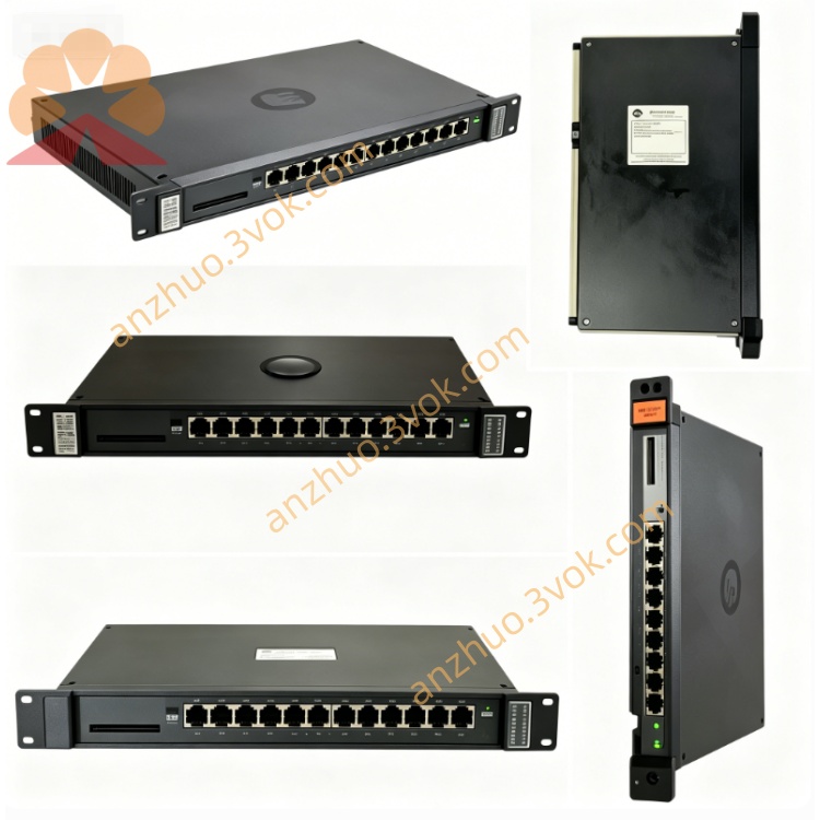
Product Overview
Model Definition
Technical Parameters
Input Channels: 4 isolated analog inputs, channel‑to‑channel and channel‑to‑logic isolation.
Signal Types: 4–20 mA DC (default), 0–10 V DC, ±5 V, ±10 V (configurable).
Resolution: 12‑bit A/D conversion, high linearity and accuracy.
Isolation Voltage: 2500 VAC RMS between field and logic sides.
Operating Voltage: 24 VDC (backplane‑powered).
Operating Temperature: 0 °C to +60 °C.
Filtering: Integral low‑pass filter (100 Hz cutoff) for noise reduction.
Installation: Single‑slot, standard AutoMax rack mount; hot‑swap capable.
Interface and Communication Configuration
Backplane Interface: Dedicated edge connector for power and data exchange via AutoMax proprietary bus.
Field Terminals: Screw terminals on front panel for analog sensor/transmitter wiring.
Communication Protocol: Communicates with the main controller over the backplane; no external network ports.
Status Indicators: LED per channel for input status; module OK and fault LEDs.
Core Functions
Acquires and conditions 4‑channel analog signals from transmitters, sensors, and transducers.
Converts analog signals to high‑resolution digital values for the control processor.
Provides galvanic isolation to protect system circuits from field noise and ground loops.
Performs signal filtering, scaling, and fault detection (open/short circuit).
Transmits real‑time process data to the controller for monitoring, PID control, and alarming.
Application Scenarios
Process industries: Steel, pulp and paper, water treatment, chemical, and power.
Factory automation: Assembly lines, material handling, and packaging machinery.
Typical signals: Flow, pressure, temperature, level, and speed transmitters.
System integration: AutoMax/DCS 5000 based plants requiring multi‑channel analog monitoring.
Operation and Maintenance Instructions
Power off the rack before installation or removal.
Insert the module into the designated slot and ensure firm backplane contact.
Wire field signals to the correct terminals, observing polarity and signal range.
Configure channel parameters (range, filtering, scaling) via system software.
Keep the rack clean, dry, and well‑ventilated; avoid corrosive gases and excessive vibration.
Inspect terminals and LED indicators periodically; replace the module with the same part number if faulty.
Do not disassemble or modify the module; repairs must be performed by authorized personnel.
Get a Quote