
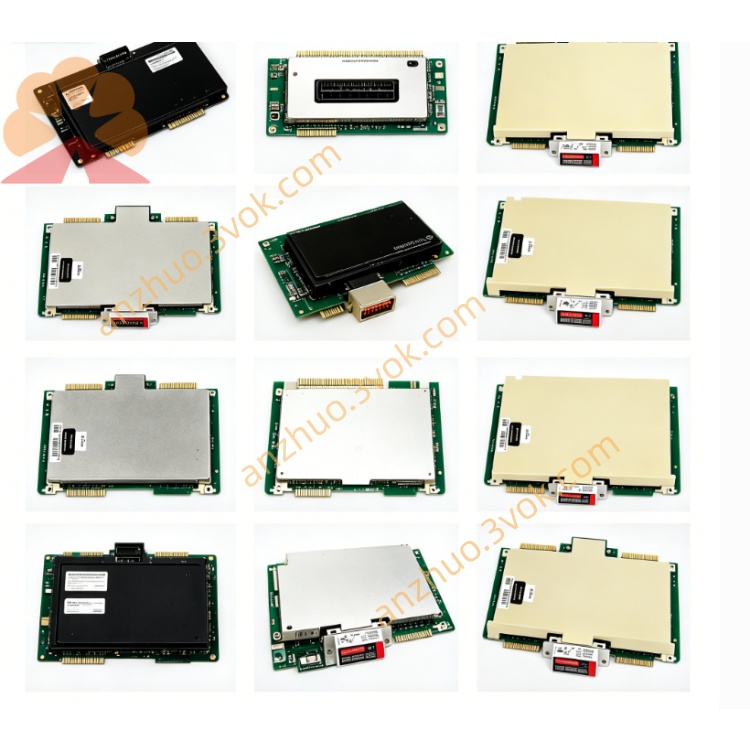
HONEYWELL 51304736-375
Description
Product Description
The 51304736-375 (also written as 51304736375) is a Low-Level Analog Input Field Terminal Assembly (FTA) for Honeywell TDC 3000/TPS/UCN DCS systems. It serves as the dedicated interface between low-level analog input modules and field low-level signal devices (such as thermocouples, RTDs, and millivolt transmitters), providing signal conditioning, galvanic isolation, and reliable wiring termination in industrial process control environments.
Model Definition
51304736-375: Official Honeywell part number. The prefix 5130 denotes the TDC 3000 DCS series, 4736 identifies the low-level analog input FTA circuit family, and 375 indicates the specific hardware revision and configuration variant.
Alternative Designations: 51304736375 (hyphen omitted), Low-Level Analog Input FTA, Thermocouple/RTD FTA.
Technical Specifications
Channels: 16 differential low-level analog input channels, supporting 16 independent field low-level signal devices.
Signal Types: Compatible with millivolt (mV) signals, thermocouple (TC) signals (J, K, T, E, R, S, B types), and RTD (PT100/PT1000) resistance signals.
Galvanic Isolation: 1500 VAC isolation between field side and system side, eliminating ground loops and suppressing EMI/RFI interference.
Termination: Crimp-type screw terminals with gold-plated contacts for secure, low-resistance connections and long-term reliability.
Loop Power: Provides 24 VDC nominal power for RTD signal conditioning circuits; open-circuit voltage 28 VDC, short-circuit current ≤ 93 mA.
Operating Temperature: -20°C to +60°C.
Storage Temperature: -40°C to +70°C.
Humidity: 5% to 95% non-condensing.
Certifications: CE, UL, CSA, RoHS compliant.
Conformal Coating: Applied (conformal coated PCB) for harsh environment protection.
Dimensions: 307 mm (12.1 in) in length, Size B form factor.
Weight: Approximately 2.2 kg.
Interface and Communication Configuration
System Interface: Connects to Honeywell low-level analog input modules (such as 51304362-150/MC-PLAM02) via a dedicated ribbon cable, enabling direct signal transfer between FTA and DCS controller.
Field Interface: 16 crimp-type terminal blocks for field wiring, each supporting differential signal connection for thermocouples, RTDs, or millivolt transmitters.
Isolation Barrier: Electrical separation between field wiring and DCS internal circuitry prevents high-voltage transients and ground potential differences from damaging system components.
No Onboard Communication Protocol: The FTA is a passive signal conditioning and termination device; all data processing and communication protocols are handled by the connected low-level analog input module and the DCS network.
Core Functions
Low-Level Signal Interface: Accepts 16 channels of millivolt, thermocouple, or RTD signals from process sensors and routes them to the DCS low-level analog input module.
Galvanic Isolation: Provides 1500 VAC isolation to eliminate ground loops, reduce electrical noise, and protect DCS hardware from field-side voltage spikes.
Signal Conditioning: Integrates precision signal conditioning circuits to amplify, filter, and linearize low-level sensor signals, ensuring accurate data acquisition.
Secure Wiring Termination: Crimp-type screw terminals ensure reliable, vibration-resistant connections for field cables, with gold-plated contacts minimizing corrosion and signal loss.
Module Compatibility: Designed as a direct, drop-in companion for Honeywell low-level analog input modules, ensuring seamless integration within TDC 3000/TPS/UCN systems.
Application Scenarios
Target Systems: Honeywell TDC 3000, TPS, and UCN Distributed Control Systems.
Industrial Sectors: Oil and gas, chemical, petrochemical, power generation, pharmaceutical, pulp and paper, and other process industries.
Field Devices: Thermocouples, RTDs, millivolt-level pressure/temperature transmitters, and other low-level process sensors.
Installation Location: DCS control room cabinets, local control panels, and field junction boxes within process plants.
Usage and Maintenance Instructions
Usage
Mounting: Install the FTA in a standard DCS cabinet or panel, ensuring adequate ventilation and clearance for wiring and cable routing.
System Connection: Connect the FTA to the low-level analog input module using the specified ribbon cable, verifying proper alignment and secure seating of connectors.
Field Wiring: Terminate field sensor cables to the FTA’s crimp terminals, following polarity and compensation guidelines for thermocouples/RTDs; tighten terminals to the recommended torque to prevent loose connections.
Power-On and Testing: Apply power to the DCS system, verify no fault alarms are present, and confirm accurate signal reading from each connected sensor via the DCS operator interface.
Maintenance
Environmental Care: Maintain a clean, dry, and well-ventilated operating environment; avoid exposure to excessive dust, moisture, and corrosive gases.
Periodic Inspection: Conduct quarterly inspections to check terminal tightness, cable condition, and isolation integrity; retighten terminals if loose and replace damaged cables promptly.
Cleaning: Remove dust and debris from the FTA surface using a dry, lint-free cloth; do not use liquid cleaners or abrasive materials that may damage the PCB or terminals.
Spare Part Storage: Store spare FTAs in anti-static bags in a cool, dry location; avoid static discharge and physical damage during handling and storage.
Get a Quote