
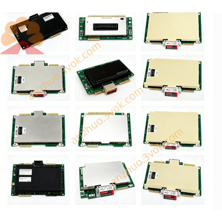
HONEYWELL 51304748-125(MU-GAIH22 / HLAI FTA GI)
Description
Product Description
Model Definition
51304748-125: The official Honeywell part number. The prefix 5130 denotes the TDC 3000 DCS series, 4748 identifies the analog input FTA circuit family, and 125 indicates the specific hardware revision and configuration variant.
MU‑GAIH22: The model alias, standing for Galvanic Isolated Analog Input FTA (High‑Level).
Alternative Designations: 51304748125 (hyphen omitted), HLAI FTA GI (Galvanic Isolated), HLAI FTA CE (Crimp Edition).
Technical Specifications
Channels: 16 differential analog input channels, supporting 16 independent field transmitters.
Signal Types: Compatible with 4–20 mA (2‑wire/self‑powered) current signals and 1–5 VDC voltage signals.
Galvanic Isolation: 1500 VAC isolation between field side and system side, eliminating ground loops and suppressing EMI/RFI interference.
Termination: Crimp‑type screw terminals with gold‑plated contacts for secure, low‑resistance connections and long‑term reliability.
Loop Power: Provides 24 VDC nominal power for 2‑wire 4–20 mA transmitters; open‑circuit voltage 28 VDC, short‑circuit current ≤ 93 mA.
Operating Temperature: -20°C to +60°C.
Storage Temperature: -40°C to +70°C.
Humidity: 5% to 95% non‑condensing.
Certifications: CE, UL, CSA, RoHS compliant.
Conformal Coating: Not applied (non‑coated PCB).
Dimensions: 307 mm (12.1 in) in length, Size B form factor.
Weight: Approximately 2 kg.
Interface and Communication Configuration
System Interface: Connects to Honeywell HLAI2 (51304754‑100) and MC‑PAIH03 (51304754‑150) high‑level analog input modules via a dedicated ribbon cable, enabling direct signal transfer between FTA and DCS controller.
Field Interface: 16 crimp‑type terminal blocks for field wiring, each supporting differential signal connection for 4–20 mA or 1–5 VDC transmitters.
Isolation Barrier: Electrical separation between field wiring and DCS internal circuitry prevents high‑voltage transients and ground potential differences from damaging system components.
No Onboard Communication Protocol: The FTA is a passive signal conditioning and termination device; all data processing and communication protocols are handled by the connected HLAI2/MC‑PAIH03 module and the DCS network.
Core Functions
Field Signal Interface: Accepts 16 channels of 4–20 mA or 1–5 VDC analog signals from process transmitters (pressure, temperature, flow, level) and routes them to the DCS input module.
Galvanic Isolation: Provides 1500 VAC isolation to eliminate ground loops, reduce electrical noise, and protect DCS hardware from field‑side voltage spikes.
Loop Power Supply: Delivers regulated 24 VDC power to 2‑wire 4–20 mA transmitters, simplifying field wiring and reducing external power requirements.
Secure Wiring Termination: Crimp‑type screw terminals ensure reliable, vibration‑resistant connections for field cables, with gold‑plated contacts minimizing corrosion and signal loss.
Module Compatibility: Designed as a direct, drop‑in companion for Honeywell HLAI2 and MC‑PAIH03 high‑level analog input modules, ensuring seamless integration within TDC 3000/TPS/UCN systems.
Application Scenarios
Target Systems: Honeywell TDC 3000, TPS, and UCN Distributed Control Systems.
Industrial Sectors: Oil and gas, chemical, petrochemical, power generation, pharmaceutical, pulp and paper, and other process industries.
Field Devices: Pressure transmitters, temperature transmitters (RTD/thermocouple with signal conditioner), flow meters, level sensors, and other 4–20 mA/1–5 VDC process transmitters.
Installation Location: DCS control room cabinets, local control panels, and field junction boxes within process plants.
Usage and Maintenance Instructions
Usage
Mounting: Install the FTA in a standard DCS cabinet or panel, ensuring adequate ventilation and clearance for wiring and cable routing.
System Connection: Connect the FTA to the HLAI2/MC‑PAIH03 module using the specified ribbon cable, verifying proper alignment and secure seating of connectors.
Field Wiring: Terminate field transmitter cables to the FTA’s crimp terminals, following polarity guidelines for 4–20 mA and 1–5 VDC signals; tighten terminals to the recommended torque to prevent loose connections.
Power‑On and Testing: Apply power to the DCS system, verify no fault alarms are present, and confirm accurate signal reading from each connected transmitter via the DCS operator interface.
Maintenance
Environmental Care: Maintain a clean, dry, and well‑ventilated operating environment; avoid exposure to excessive dust, moisture, and corrosive gases.
Periodic Inspection: Conduct quarterly inspections to check terminal tightness, cable condition, and isolation integrity; retighten terminals if loose and replace damaged cables promptly.
Cleaning: Remove dust and debris from the FTA surface using a dry, lint‑free cloth; do not use liquid cleaners or abrasive materials that may damage the PCB or terminals.
Spare Part Storage: Store spare FTAs in anti‑static bags in a cool, dry location; avoid static discharge and physical damage during handling and storage.
Get a Quote