12P1732X042
Description
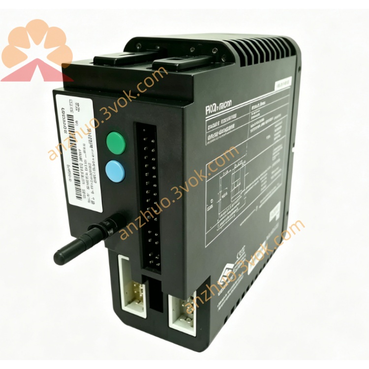
1. Product Overview
2. Main Features
8 fully isolated RTD input channels
Support standard RTD types: PT100, PT200, PT500, PT1000, Cu50, Cu100
Support 2-wire, 3-wire and 4-wire connection modes
16-bit high resolution, excellent measurement linearity
Built-in high-precision constant current source, low temperature drift
1500 VDC isolation between field side and internal circuit
Software configurable sensor type, wiring mode, measuring range and digital filter
Integrated fault diagnosis: open circuit, short circuit and over-limit detection
Industrial wide temperature design, long-term stable operation
Standard 35 mm DIN rail mounting, compact and easy installation
Comply with industrial EMC anti-interference standard
3. Technical Specifications
3.1 General Parameters
3.2 RTD Input Specifications
3.3 Communication & Diagnosis
4. Safety Precautions
Installation, wiring and maintenance must be operated by qualified professional technicians.
Disconnect all power before wiring, disassembly or module replacement to avoid electric shock and module damage.
Do not install in flammable, explosive, dusty or corrosive environment without explosion-proof certification.
Use shielded twisted-pair cables for RTD signal wiring; separate signal cables from power cables.
The shield layer of signal cable shall be grounded at single end to avoid circulating current interference.
Strictly follow 2-wire / 3-wire / 4-wire standard wiring; wrong connection will cause large measurement error.
Do not input over-limit resistance or voltage to each channel.
Do not disassemble or modify the internal circuit structure without official authorization.
5. Installation and Terminal Definition
5.1 DIN Rail Installation
Fix 35 mm standard DIN rail firmly on the installation panel.
Hook the upper buckle of the module onto the DIN rail edge.
Press downward until the bottom lock snaps tightly.
Shake slightly to confirm firm installation without looseness.
5.2 Terminal Pin Assignment
5.3 Wiring Instructions
Strip about 6 mm insulation of wire ends, insert into corresponding terminals and tighten screws moderately.
2-wire RTD: connect two lines to terminal A and B, terminal C empty.
3-wire RTD: three lines connect to A, B, C respectively.
4-wire RTD: follow standard 4-wire distribution to A, B, C terminals as defined.
Use shielded twisted-pair cable for long-distance transmission, single-end grounding for shielding layer.
Avoid routing signal cables parallel with high-voltage AC power lines to reduce interference.
6. Parameter Configuration
Add 12P1732X042 module in DCS / PLC configuration software.
Set module address, rack and slot number according to actual hardware position.
Configure each channel parameters:
Select RTD sensor type
Choose 2-wire / 3-wire / 4-wire wiring mode
Set temperature engineering range and unit (℃ / ℉)
Adjust digital filter time constant
Enable open circuit and short circuit fault alarm
Download configuration to controller and module.
Check real-time temperature value to verify normal measurement.
7. Operation Description
7.1 Power-on Self-test
7.2 Main Functions
Accurately collect resistance signal from field RTD sensors.
Automatically convert resistance value to standard temperature value.
Complete line resistance compensation, digital filtering and linear processing internally.
Upload temperature data to DCS / PLC system in real time.
Realize channel fault detection and alarm uploading.
Accept remote parameter configuration to adapt to different sensor types.
7.3 Indicator Description
8. Daily Maintenance
Regularly check terminal tightness, oxidation and corrosion condition.
Clean module surface dust with dry soft cloth only, no liquid or chemical solvent.
Keep ambient temperature and humidity within specified range.
Periodically inspect signal cables for aging and poor contact, replace in time if damaged.
Regular calibration with standard resistance box is recommended to ensure measurement accuracy.
9. Troubleshooting
- Power indicator not onCause: No 24VDC input, reverse polarity or broken power wireSolution: Check power supply and correct wiring polarity
- Module cannot be recognized by systemCause: Wrong address setting, loose backplane contactSolution: Confirm module address, re-install and lock the module
- Temperature value unstable or jumpingCause: Loose wiring, no shielding or strong electromagnetic interferenceSolution: Fasten terminals, use shielded cable and single-end grounding
- Large temperature measurement deviationCause: Wrong RTD type or wrong wiring mode configurationSolution: Re-select sensor type and match 2/3/4-wire mode
- Channel open circuit alarmCause: RTD sensor damaged or signal wire brokenSolution: Check field sensor and wiring connection
Get a Quote