12P1731X082
Description
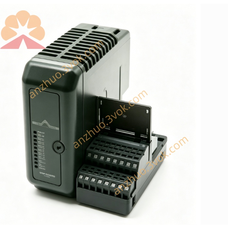
1. Product Overview
2. Main Features
8 fully isolated universal input channels
Support multiple thermocouple types: J, K, T, E, R, S, B, N
Support millivolt signal input: ±2mV, ±5mV, ±10mV, ±20mV, ±50mV, ±100mV
16-bit high-resolution analog-to-digital conversion
Built-in precise cold junction compensation (CJC) for thermocouple measurement
1500VDC isolation between field side and internal circuit, channel-to-channel isolation
Software configurable sensor type, measuring range and digital filter parameter
Built-in channel diagnosis: open circuit, short circuit, over-range and under-range fault detection
Low temperature drift, high long-term stability
Standard DIN rail mounting, compact structure, easy installation and wiring
Meet industrial EMC electromagnetic compatibility requirements
3. Technical Specifications
3.1 General Parameters
3.2 Input Specifications
3.3 Communication & Diagnosis
4. Safety Precautions
Installation, wiring and maintenance must be performed by qualified professional technicians.
Cut off all power supply before wiring, disassembly or module replacement to avoid electric shock and equipment damage.
Do not install the module in flammable, explosive, dusty or strong corrosive gas environment without explosion-proof certification.
Use shielded twisted-pair cable for thermocouple and millivolt signal wiring.
Signal cables and power cables shall be laid separately to reduce electromagnetic interference.
The shielding layer of signal cable should be grounded at single end to avoid circulating current interference.
Do not exceed the maximum input voltage range of each channel to prevent module burnout.
It is forbidden to disassemble, modify or refit the internal circuit of the module without official authorization.
5. Installation and Terminal Definition
5.1 DIN Rail Installation
Fix the 35mm standard DIN rail firmly on the installation panel.
Hang the upper bayonet of the module on the edge of the DIN rail.
Press the module downward until the bottom locking buckle is tightly clamped.
Shake the module slightly to confirm firm installation without loosening.
5.2 Terminal Pin Assignment
5.3 Wiring Instructions
Strip about 6mm insulation layer at the wire end.
Loosen the terminal screws, insert the wires into the corresponding terminals, and tighten the screws moderately.
For thermocouple connection, use matched thermocouple compensation wire, correctly connect positive and negative polarity.
For millivolt weak signal, use shielded twisted-pair wire, connect signal positive and negative to channel corresponding terminals.
Connect the cable shielding layer to the shield ground terminal, and only ground at the module side.
Avoid wiring near high-power equipment and AC power lines to reduce interference.
6. Parameter Configuration
Add the module device in DCS or PLC configuration software.
Set module station address and rack slot number according to actual hardware position.
Configure each channel parameter one by one:
Select input type: thermocouple type or millivolt range
Set engineering unit: Celsius, Fahrenheit or millivolt
Configure digital filter time constant
Enable open circuit, short circuit and over-range alarm function
Download the configuration to the controller and module.
After configuration, check each channel measured value to confirm normal collection.
7. Operation Description
7.1 Power-on Self-test
7.2 Working Function
Collect temperature signal from thermocouple or weak millivolt signal from field instrument.
Complete cold junction compensation, linear conversion and digital filtering internally.
Convert analog signal into digital data and upload to DCS/PLC system in real time.
Realize channel fault diagnosis and upload alarm information when abnormal.
Accept system configuration parameters to realize range switching and function setting.
7.3 Indicator Status Description
8. Daily Maintenance
Regularly check whether the module terminals are loose, oxidized or corroded.
Clean the dust on the module surface regularly with dry soft cloth, do not use liquid and chemical solvent.
Keep the installation environment temperature and humidity within the specified range.
Regularly inspect signal cables for aging, damage and poor contact, replace in time if abnormal.
Calibrate the module regularly with standard millivolt signal source to ensure measurement accuracy.
9. Troubleshooting
- No power indicatorCause: 24VDC power loss, reverse power polarity or power line breakageSolution: Check power circuit, correct wiring polarity
- Communication failure, module not recognizedCause: Address setting error, backplane connection loose or communication line faultSolution: Confirm module address, re-seat module and check communication wiring
- Temperature or millivolt data unstableCause: Signal wiring loose, no shielding measures or strong electromagnetic interferenceSolution: Fasten terminals, use shielded cable and single-end grounding, stay away from interference source
- Measurement value deviation too largeCause: Wrong thermocouple type or range configuration, cold junction compensation abnormalSolution: Reconfigure channel type and range, check CJC circuit
- Channel open circuit alarmCause: Thermocouple wire broken, signal wire disconnected or poor contactSolution: Check field sensor and wiring connection
Get a Quote