
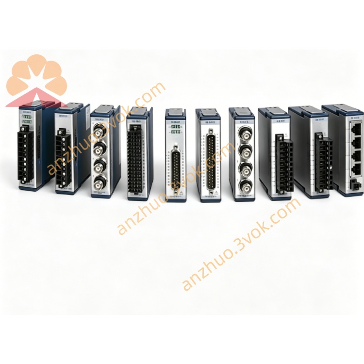
NI SCXI-1339 Front Terminal Block for SCXI-1129 Matrix Switch
Description
Product Introduction
The NI SCXI-1339 is a shielded matrix switch terminal block specifically designed for the SCXI-1129 high-density matrix switch module. It enables the module to be configured as a dual 4×32 two-wire independent matrix, similar in function to SCXI-1337 but with a slightly different layout and terminal definitions. The standard part number is 777687-39. It features a full metal shielded housing with a stress release structure, making it suitable for high-reliability and medium-high density signal routing scenarios.
Model Interpretation
SCXI: Instrument Signal Conditioning Expansion Platform (NI Modular Signal Conditioning Series).
13xx: SCXI System Front-End Mountable Terminal Block Series.
SCXI-1339: Dedicated terminal block for SCXI-1129, enabling the configuration of a dual 4×32 two-wire matrix. Technical Specifications
Electrical parameters
Adapter module: SCXI-1129
Matrix configuration: Dual 4×32 two-wire independent matrix (two completely isolated groups)
Channel-to-ground / Channel-to-channel voltage: 150 V (CAT I), capable of withstanding 800 V pulse voltage
Maximum current per channel: 2 A (AC/DC)
Triggering and scanning: With advanced scanning output, external input trigger terminals
Expansion interface: Supports row/column expansion, can be combined into larger matrices
Adapter wire gauge: 26 AWG to 14 AWG
Cold junction compensation: None
Mechanical and environmental parameters
Installation: SCXI standard front-end installation, 2 wing-type screws for fixation
Operating temperature: 0 ℃ to 50 ℃
Storage temperature: -20 ℃ to 70 ℃
Relative humidity: 10% to 90% (no condensation)
Shielding: Full metal enclosure, suppressing EMI/RFI
Safety compliance: IEC 61010-1, UL 61010-1; EMC: EN 55011 Class A, EN 61326
Interface and communication configuration
Front: Dual 4×32 matrix screw terminals, trigger terminals, expansion interface, with stress release and safety grounding tabs
Back: Dedicated connectors directly connected to SCXI-1129, no additional wiring required
Expansion: Supports row/column expansion, can be combined into dual 4×64, 8×32, etc. matrices
Software compatibility: Plug-and-play, compatible with NI-DAQmx driver, supports LabVIEW, C/C++, LabWindows/CVI, etc. development environments
Core functions
Realize the dual 4×32 independent matrix configuration of SCXI-1129, providing two isolated medium-density signal routing capabilities.
Support flexible row/column expansion to meet the channel expansion requirements of parallel test systems.
Full metal shielding structure, effectively suppressing electromagnetic interference, ensuring signal integrity in complex industrial environments.
Screw terminal connection is reliable, resistant to vibration, with stress release design, suitable for long-term online operation.
Integrated trigger and scanning output terminals, facilitating synchronous control of multi-device systems. Applicable scenarios
Build a dual 4×32 matrix switching system in conjunction with SCXI-1129 for dual-channel parallel signal routing and functional testing.
This is applicable to fields such as semiconductor testing, automotive electronics, and aerospace, which require two independent signal switching systems.
Industrial automation test platforms, laboratory multi-channel calibration and signal distribution equipment.
Large-scale test systems that need to isolate dual channels while balancing density and flexibility.
User Manual for Use and Maintenance Instruction Manual
Before installation, cut off all power supplies. Align the terminal board with the front interface of the module and insert it smoothly. Tighten the fixing screws.
Complete the two-wire connection according to the terminal markings. Ensure reliable grounding of the shielding terminal and the safety grounding piece to reduce interference.
If expansion is needed, use the dedicated extension cable / plug to connect the row and column expansion interface to ensure a secure connection.
Configure the dual matrix mode, trigger parameters and scan sequence in the software. After completion, data can be collected.
Maintenance instructions
Place the equipment in a dry and ventilated area. Maintain the temperature and humidity within the rated range. Keep away from strong electromagnetic sources, dust and corrosive gases.
Regularly check if the connection screws are loose, if the terminals are oxidized, and if the insulation layer of the cables is damaged. Address any issues promptly.
Cleaning should be done while the power is off. Use isopropyl alcohol to wipe the surface and terminals. Allow it to dry completely before reconnecting the power.
When the equipment is idle for a long time, remove the terminal board and place it in an anti-static bag. Store it in a cool and dry environment.
Get a Quote