
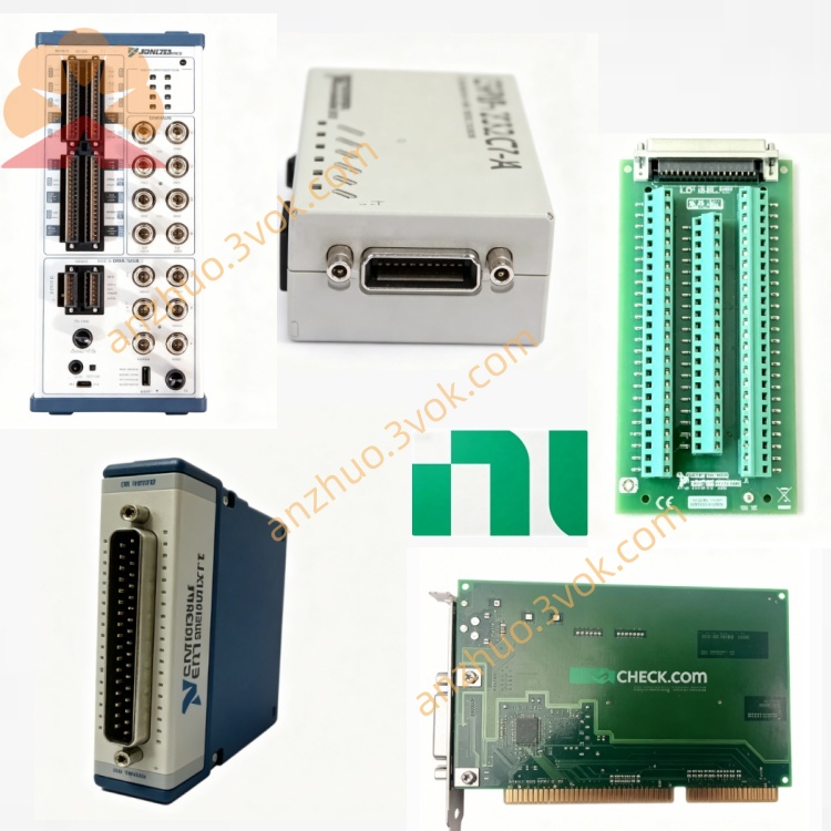
NI SCXI-1334 Terminal Block for SCXI Matrix Switch
Description
Product Introduction
The NI SCXI-1334 is a shielded terminal block specifically designed to be used with the SCXI-1127 and SCXI-1128 multiplexing and matrix switch modules. This terminal block is tailored for two-wire resistance measurement and is equipped with an onboard excitation resistor, which can provide a stable driving signal for resistance sensors. The device features a full metal casing and exhibits excellent electromagnetic interference suppression capabilities. Its voltage withstand and current-carrying ratings meet industrial requirements, making it suitable for routine resistance signal switching and acquisition in industrial settings and laboratories. The standard part number for this product is 777687-34.
Model Interpretation
SCXI is the abbreviation for the Instrument Signal Conditioning Expansion Platform, which is part of the NI modular signal conditioning hardware series. The 13xx series uniformly represents the front-end terminal blocks that are compatible with the SCXI system. SCXI-1334 is a dedicated terminal block for two-wire resistance measurement and is compatible with the SCXI-1127 and SCXI-1128 switch modules. Technical Specifications
Electrical parameters
The adapter module is SCXI-1127 and SCXI-1128. The terminal board is equipped with corresponding terminals and supports two-wire signal connection. It has an internal excitation resistor to meet the driving requirements for resistance measurement. The rated working voltage follows the CAT II standard and can reach up to 300V. The maximum current for a single channel AC and DC is 2A. The product mainly adopts a 32-channel two-wire wiring method and does not integrate a cold junction compensation sensor. The back panel uses a dedicated connector that can directly connect to the corresponding module. The cable specification range for the adapter is 26 AWG to 14 AWG.
Mechanical and environmental parameters
The product adopts the SCXI standard size and is installed at the front end of the corresponding module, fixed by two wing-type screws on the top and bottom. The working temperature range is 0 degrees Celsius to 50 degrees Celsius, and the storage temperature range is -20 degrees Celsius to 70 degrees Celsius. The relative humidity of the working environment is 5% to 90%, and condensation is not allowed in the environment. The full metal shell can effectively resist electromagnetic radiation interference and complies with IEC 61010-1, UL 61010-1, CAN/CSA-C22.2 No.1010.1 safety standards.
Interface and communication configuration
The front of the device is equipped with two-wire signal terminals, grounding terminals, and auxiliary connection terminals. There are no additional dip switches or jumpers. The back interface directly connects to the SCXI-1127 and SCXI-1128 modules to achieve signal transmission, without the need for additional communication circuits. The product is plug-and-play and does not require separate hardware settings. It is compatible with NI-DAQmx driver programs and can be used normally in mainstream development environments such as LabVIEW, C/C++, LabWindows/CVI.
Core functions
Based on the two-wire wiring circuit, it realizes the collection and switching of conventional resistance signals, suitable for most general resistance measurement scenarios. The onboard excitation resistor provides a stable excitation signal for resistance-type sensors, ensuring stable measurement data. It has a 300V voltage withstand and 2A current carrying capacity, meeting the requirements of conventional industrial signal transmission. The metal shielding structure can weaken external electromagnetic interference and maintain signal transmission quality in complex working conditions. The connection terminals have a stress release structure, are securely connected, have strong vibration resistance, and are suitable for long-term online operation. Applicable scenarios
Combined with SCXI-1127 and SCXI-1128, a multi-channel resistance scanning system is built to complete the detection of general resistance signals. It is applied in industrial automation scenarios to achieve signal acquisition for simple thermoresistors and conventional strain sensors. It can be used in test fixtures for semiconductor, automotive, and aerospace fields to complete resistance detection of components. It is also applicable to routine laboratory tests, equipment calibration, and general signal routing, etc.
User Manual for Use and Maintenance Instruction Manual
Before installation, all power supplies of the equipment must be cut off. Align the terminal board with the front interface of the module and insert it steadily. Tighten the fixing screws on both sides. Select cables within the specified range, complete the two-wire connection according to the terminal markings, reliably connect the shield terminal to the ground to reduce external interference. Set the software in the accompanying program to the two-wire measurement mode, and after configuration, data collection can be carried out.
Maintenance Instructions
The equipment should be placed in a dry and ventilated area, with temperature and humidity maintained within the rated range. Keep away from strong electromagnetic sources, dust and corrosive gases. Regularly check if the connection screws are loose, if the terminals are oxidized, and if the insulation layer of the cables is damaged. Address any issues promptly. Cleaning operations must be performed with the power off. Use isopropyl alcohol to wipe the equipment surface and connection terminals, and allow it to dry completely before re-powering. When left idle for a long time, remove the terminal board, place it in an anti-static bag, and store it in a cool and dry environment.
Get a Quote