
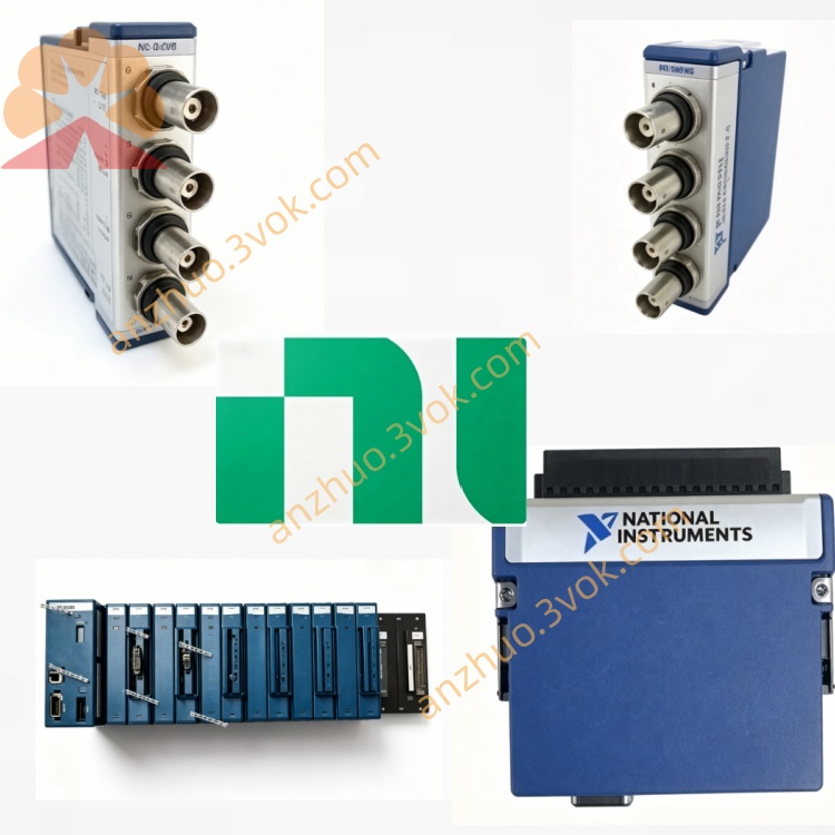
NI SCXI-1163 32-Channel Solid-State Relay Module
Description
I. Product Introduction
NI SCXI-1163 is a 32-channel photo-isolated TTL/CMOS digital output module of the SCXI series, used for outputting low-voltage logic control signals. It features strong isolation protection to prevent high-voltage and ground loop from damaging the main control system. There is also a counterpart with the same model number, SCXI-1163R, which is a 32-channel solid-state relay output board and can directly switch 240 VAC/VDC high-voltage loads. The SCXI-1163 has been discontinued and spare parts and second-hand equipment are common.
II. Model Interpretation
SCXI: Instrument Signal Conditioning Expansion Series.
1163: 32-channel photo-isolated digital output basic model (TTL/CMOS).
1163R: R=Relay, solid-state relay output board, supporting high-voltage switching.
Part Number: SCXI-1163 standard number 776572-63, 1163R is 776572-63R.
III. Technical Parameters (SCXI-1163)
Channels: 32-channel photo-isolated digital output, divided into 8 independent isolation groups (Bank), each group 4 channels.
Output Levels: TTL/CMOS compatible, high level ≥ 2.4 V, low level ≤ 0.4 V.
Drive Current: Maximum 16 mA per channel.
Isolation: Group-to-group, group-to-backplane 450 VAC working isolation, 1900 Vrms breakdown isolation, eliminating ground loop.
Response Time: Typical 0.5 ms, maximum 1 ms.
Frequency: Maximum 1 kHz pulse output.
Power Supply: +5 VDC (backplane power supply), power consumption approximately 2 W.
Temperature: Working 0~55 ℃; Storage -40~85 ℃.
IV. Interface and Configuration
Front Panel: 50-pin DIN, recommended terminal block SCXI-1327 (screw wiring, isolation adapter).
Back Panel: Standard SCXI bus, supports multi-module cascading, address configuration, power supply and status reading.
Driver: Compatible with NI-DAQmx/NI-SWITCH, supports LabVIEW, C/C++, .NET.
Configuration: Built-in jumpers for setting output levels and isolation modes.
V. Core Functions
Low-voltage logic output: Directly output TTL/CMOS levels to control low-voltage relays, LEDs, optocoupler inputs, etc.
Grouped strong isolation: 8 independent isolation groups, 450 V isolation between groups, protecting the main control equipment from high-voltage surges.
High interference resistance: Photo-isolation + high insulation design, resisting electromagnetic interference from motors, frequency converters, etc.
High-density control: Single module 32 channels, multi-module cascading up to hundreds of points, suitable for large-scale logic control.
Compatible with 1163R: The same chassis can accommodate 1163 (logic) and 1163R (high-voltage relays), mixed control of high and low voltage equipment.
VI. Application Scenarios
Industrial Automation: PLC/DAQ system low-voltage relay, contactor, electromagnetic valve coil control (24 VDC).
Test Measurement: ATE equipment channel selection, relay matrix, indicator lights, alarm buzzers drive.
Instrument Control: External instrument trigger, enable, reset signal output, logic level matching.
Strong interference environment: Power plants, petrochemicals, rail transit, etc. sites, isolating low-voltage control from high-voltage circuits.
VII. Use and Maintenance Use
Power-off installation, set module address to prevent conflicts.
Separate the high-voltage and low-voltage circuits for wiring. 1163 uses SCXI-1327, 1163R uses SCXI-1326 for the high-voltage terminal block.
Select the TTL/CMOS mode for the jumper, and power on after confirming the output level.
Prohibit hot plugging to avoid surge damage to optocouplers or solid-state relays. Maintenance
Environment: Well-ventilated and dry, temperature range 0–55 ℃, humidity range 5%–95% without condensation.
Regular inspections: Check terminals, cables, connectors, secure wiring, and clean dust.
Troubleshooting: For abnormal output, first check external load and wiring, then check module jumpers and driver configuration.
Get a Quote