
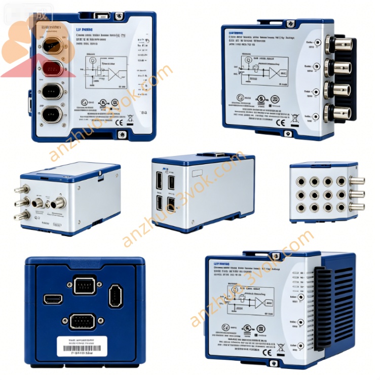
NI SCXI-1162 32-Channel Optically Isolated Digital Input Module
Description
I. Product Introduction
NI SCXI-1162 is a 32-channel photoelectric isolation digital input module of the SCXI series. It adopts an optocoupler isolation design, specifically for collecting industrial digital levels, switch states, and pulse signals, and has high anti-interference capability. The module is compatible with various industrial level standards and can be adapted to various passive contacts and active digital signals in the field. The overall structure is compact, suitable for distributed digital quantity collection in industrial sites. This model has been discontinued and can provide maintenance services. The inventory and second-hand equipment can still be used normally.
II. Model Interpretation
SCXI is the identification mark of the instrument signal conditioning expansion series. 1162 is an exclusive model of this series, representing a 32-channel photoelectric isolation digital input module. The series also includes power relay modules and mixed digital IO modules, and can be selected based on the input and output types. The standard component number of the product is 776572-62.
III. Technical Parameters
The module integrates 32 independent digital input channels, and each channel is equipped with an optocoupler isolation device. The isolation voltage between the channel and the backplane can reach 250 volts RMS, meeting industrial safety standards. It supports a rich range of input level types, which can be adapted to TTL levels, 24-volt industrial levels, 120-volt AC and 240-volt AC signals. The input threshold can be adapted to mainstream industrial standards, and the input response speed is stable, with a maximum input pulse frequency of up to 1 kHz. The single-channel input leakage current is extremely low, and passive dry contacts and active voltage signals can be normally recognized. The module is powered by the SCXI chassis backplane, and the overall power consumption is low. The standard working temperature range is 0°C to 55°C, and the storage temperature range is -40°C to 85°C. The working environment humidity requirement is 5% to 95% without condensation.
IV. Interface and Communication Configuration
The module's front side is equipped with a 96-pin DIN connector. It is usually combined with a dedicated terminal block to complete wiring connection and screw connection, and can be adapted to different voltage levels of on-site lines. The back side is connected to the SCXI standard chassis backplane bus, relying on the bus to complete power supply, data transmission, and module address identification. It supports multi-module installation in the same chassis and cascading expansion. The module has no independent external communication interface. It relies on the SCXI bus to interact with the backend DAQ equipment, and is paired with NI-DAQmx or NI-SWITCH driver software to complete parameter configuration, status reading, and is compatible with various mainstream programming development environments.
V. Core Functions
The all-channel photoelectric isolation design effectively blocks ground loops and significantly resists electromagnetic interference generated by industrial site equipment such as motors and frequency converters, ensuring stable digital signal collection. The 32 high-density channel design allows a single module to achieve the monitoring of a large number of points, and with the cascading of multiple modules, the channel scale can be flexibly expanded. It is compatible with various industrial levels of AC and DC and passive contact signals, with strong versatility, and can be adapted to different types of on-site equipment. The circuit structure is simple and reliable, meeting the requirements of conventional switch quantities and low-speed pulse collection, and has good long-term continuous operation stability. Standard bus connection allows it to be used in combination with SCXI series analog input, relay switch, etc. modules to build a complete mixed signal acquisition control system.
VI. Application Scenarios
It is widely used in industrial production lines, assembly lines for travel switches, proximity switches, button contact state monitoring. It can collect relay auxiliary contacts, circuit breaker on-off states of distribution cabinets, electrical equipment, and be used for equipment operation and fault alarm. It is compatible with various digital feedback signals and low-speed pulse counting signals of automation equipment. In strong interference environments such as factory workshops and power rooms, it can complete distributed multi-point digital quantity inspection. It can also be used in laboratories and test platforms for centralized collection and monitoring of multiple digital state signals.
VII. Usage and Maintenance Instructions Instruction Manual
Before installing the module, the power supply of the SCXI chassis must be cut off. Insert the module into the corresponding slot and tighten the fixing screws. When using multiple modules simultaneously, set independent addresses to prevent address conflicts. Connect the wires according to the voltage level of the signals, distinguish between AC and DC circuits, and arrange the strong and weak lines separately. Ensure the wiring is firm and reliable. In the accompanying software, confirm the input level type and complete the channel configuration before powering on and running. During daily use, try to avoid plugging and unplugging the module while powered on to prevent damage to the optocoupler devices caused by instantaneous surges.
Maintenance Instructions
Maintain the daily usage environment with good ventilation and dryness, away from corrosive gases, intense vibration and high-temperature heat sources, and avoid condensation inside the equipment. Regularly inspect the wiring terminals, connectors and external cables, check for aging, loosening, oxidation phenomena in the lines, and promptly tighten and replace them. Regularly clean the dust on the module surface to ensure normal heat dissipation. If there is abnormal signal reading in the channel, prioritize checking the external lines, power supply voltage and contact status, and then investigate the module installation and driver configuration. Before the equipment is left idle for a long time, disconnect all power sources and external lines, clean them, and store them properly in a cool and dry environment.
Get a Quote