
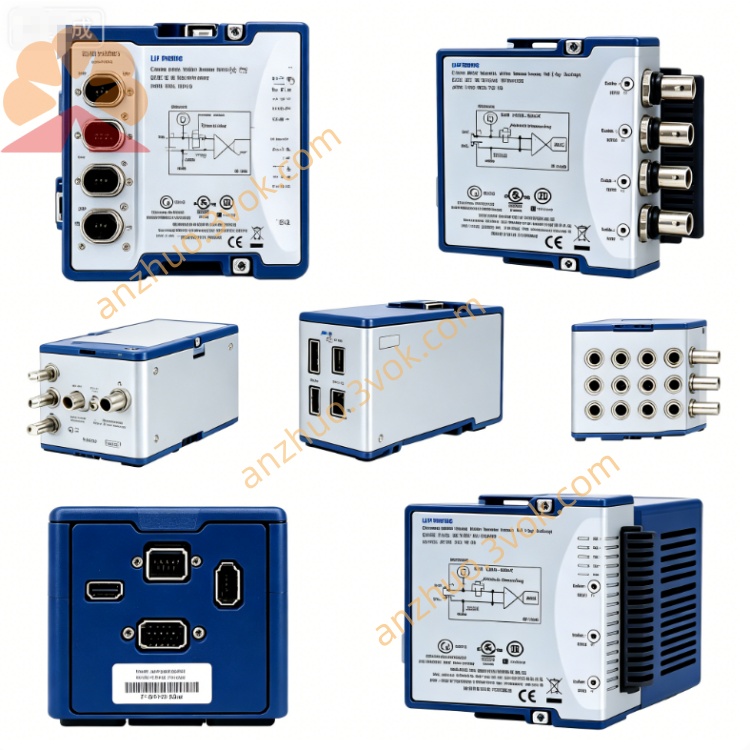
NI PXIe-8135-782450-04 High-performance PXIe Embedded Controller
Description
Product Introduction
The NI PXIe-8135-782450-04 is a standard 3U-sized PXIe embedded controller, equipped with an Intel Core i7 processor. It serves as the main control unit for the PXIe test chassis and can be directly integrated within the chassis without the need for an external computer. This model relies on stable computing performance and a rich set of onboard interfaces to achieve functions such as overall control, data processing, and device interconnection. The 782450-04 version is a standard configuration with 4GB of memory and a 256GB solid-state drive. It is suitable for various mid-to-high-end automated testing and measurement systems.
Model Interpretation
NI is the brand name of National Instruments. PXIe refers to the PXI high-speed instrument standard based on the PCI Express bus. 8135 is the exclusive series number for this embedded controller. 782450 is the hardware base component number, and the suffix - 04 represents the overall configuration specification, corresponding to 4GB of running memory and 256GB of solid-state drive, and it is also a standard working temperature version.
Technical Parameters
The device is equipped with an Intel Core i7-3610QE quad-core processor with a base frequency of 2.3GHz and a maximum single-core dynamic frequency of 3.3GHz. It is configured with multiple levels of high-speed cache. The standard configuration includes 4GB DDR3L memory, and the hardware can be expanded up to 16GB in dual-channel mode. It has a built-in 256GB solid-state drive for local storage. The module uses the second-generation x4 specification PXIe bus, with a maximum system bidirectional bandwidth of 8GB/s and a single-slot bandwidth of 2GB/s. It integrates Intel HD Graphics 4000 integrated graphics, powered directly by the PXIe chassis backplane, with a typical operating power consumption of 60W. The entire machine is in a standard 3U PXIe module form, weighing approximately 1.5 kilograms. The normal operating temperature range is 5 degrees Celsius to 50 degrees Celsius, the extended operating temperature range is 0 degrees Celsius to 55 degrees Celsius, the storage temperature range is from -40 degrees Celsius to 70 degrees Celsius, and the operating environment humidity requirement is 10% to 90% without condensation. It natively supports Windows systems and the LabVIEW real-time operating system.
Interface and Communication Configuration
The front panel of the module integrates multiple commonly used peripheral interfaces, including two sets of gigabit Ethernet interfaces, six sets of USB interfaces, two sets of USB3.0 specifications, four sets of USB2.0 specifications, one RS-232 serial port, one parallel port, two sets of DisplayPort video output interfaces, and audio input and output interfaces, PS/2 interfaces, device reset buttons, and power status indicator lights. The internal connection is through the standard x4 PXIe Gen2 bus to the chassis backplane, supporting DMA high-speed data transmission and multi-module synchronization. Based on the PXIe bus, various functional modules can be expanded, and the software layer is compatible with NI's complete driver tools. It can complete device identification, parameter configuration, and status management through NI MAX, supporting mainstream development environments such as LabVIEW, C/C++, and Python.
Core Functions
Integrated main control capability, which can be directly used as the core controller of the PXIe system, eliminating external industrial control devices, simplifying the system structure and saving cabinet space. The multi-core processor combined with high-bandwidth buses has strong data processing and throughput capabilities, capable of meeting requirements for high-speed data acquisition, complex signal analysis, and real-time computing. The onboard interfaces are of various types and can be directly connected to displays, keyboards, mice, printers, external instruments and other peripheral devices to expand the usage scenarios. The solid-state hard drive has excellent read and write speeds, enabling local storage, caching and quick retrieval of test data. It supports two operating modes: conventional desktop system and real-time operating system, catering to both program development and debugging as well as high-deterministic real-time control requirements. It is compatible with the backplane clock and trigger bus of the PXIe chassis, enabling high-precision timing synchronization of multiple modules within the chassis.
Six. Application Scenarios
It is applicable to the functional testing and parameter detection systems of various chips and wafers in the semiconductor industry, undertaking the main control and data processing tasks. It can serve as the main controller for RF, microwave, and communication testing equipment, and be applied in the product development and testing of mobile communications, radar, and satellite communication. It serves the aerospace and defense fields, used for the testing and control of aircraft, electronic countermeasure equipment, and navigation systems. In the automotive electronics field, it supports the automatic testing of autonomous driving radars, on-board electronic control units, and battery power supplies. It can also be applied in the industrial automation field, building online detection, machine vision, motion control, and distributed data acquisition systems.
Seven. Usage and Maintenance Instructions Instruction Manual
Before installing the equipment, the power supply of the PXIe chassis must be cut off. Insert the module smoothly into the corresponding slot of the chassis and tighten the fixing screws. The installation position should be as close as possible to the fan area of the chassis to ensure the cooling effect. Connect the external lines such as monitors, network cables, USB peripherals, serial port devices, etc. according to the requirements, and confirm that the connections are stable before connecting the power supply of the entire machine. After powering on, the system can automatically recognize the hardware, and with the corresponding drivers and application software, it can start working. You can choose to run the regular system or real-time operating system according to your usage needs. When conducting multi-module synchronization tests, complete the configuration of parameters such as clocks and trigger routes in the software.
Maintenance Instructions
During daily use, keep the front panel interfaces and the surface of the chassis clean. Use a dry soft cloth to wipe the dust regularly to avoid debris entering the interface. Regularly check all external cables and connectors to see if there are any loose, aged, or poor contact issues. Address any abnormalities promptly. Strictly control the temperature and humidity of the working environment. Stay away from strong electromagnetic interference, intense vibration, and corrosive gases to ensure the smooth airflow of the chassis. When the equipment experiences running stalling or abnormal data transmission, check the memory, hard disk status, bus connections, and driver programs one by one. When there is a communication fault at the interface, check whether the corresponding lines and interfaces are damaged. If the equipment is to be left idle for a long time, cut off the power supply of the entire machine, remove the module, and store it in a dry and cool environment. Take precautions against static electricity and avoid squeezing or bumping. Do not plug or unplug the module or any signal lines while the equipment is powered on to prevent hardware damage.
Get a Quote