
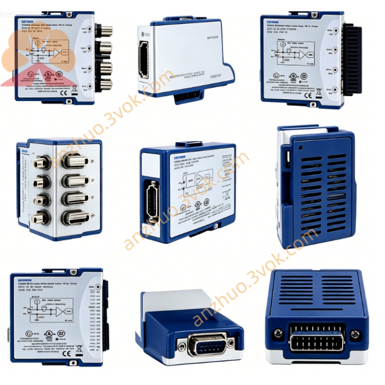
NI PXIe-6556-781949-02 High-Speed Digital Waveform Generator & Analyzer Module
Description
I. Product Introduction
The NI PXIe-6556-781949-02 is a 24-channel, 200 MHz, PPMU (Pin-Per-Module Unit) equipped high-speed digital waveform generator/analyzer, belonging to the PXIe high-performance digital testing instrument. 781949-02 is the version with 64 MB large-capacity storage per channel, capable of simultaneously generating and collecting high-speed digital signals, and completing DC parameter testing, suitable for semiconductor, digital chip verification and mass production testing.
II. Model Interpretation
NI: Brand of National Instruments (美国国家仪器) .
PXIe: PXI Express, high-speed modular instrument bus standard.
6556: Product serial number, representing 24-channel, 200 MHz, digital waveform generator/analyzer with PPMU.
781949: Basic component number.
-02: Suffix, indicating 64 MB on-chip memory per channel (-01 is 8 MB per channel).
III. Technical Parameters
Channel Configuration: 24 bidirectional digital channels, each channel integrated with independent PPMU; 4 PPMU-enabled PFI channels (docs-be.ni.com).
Clock Rate: Up to 200 MHz (5 ns edge resolution), data rate 200 Mbps.
Voltage Range: Programmable -2 V to +7 V (or -1 V to +7 V), supports 3.3 V/5 V logic levels.
Onboard Memory: 64 MB per channel (781949-02).
PPMU Accuracy: Current measurement accuracy 20 nA, voltage accuracy ±1 mV, supports continuity, IV curve testing.
Timing Jitter: Typical 24 ps RMS (onboard clock) NI.
Input Protection: -3 V to +8.5 V, supports 0–5 V continuous short-circuit protection.
Physical Specifications: 3U PXIe module, size 21.6×2.0×13.0 cm, weight approximately 794 g.
Environmental Parameters: Operating temperature 0–55°C, storage -40–70°C, humidity 10%–90% without condensation NI.
IV. Interface and Communication Configuration
Front Panel Connectors:
DDC (68-pin VHDCI): 24 digital channels, clock, trigger, event signals NI.
REMOTE SENSE (68-pin VHDCI): PPMU remote sensing channel, used for high-precision DC measurement NI.
AUX I/O (Combicon): External forced / sensing, analog calibration interface NI.
CLK IN/OUT (SMA): External reference clock input/output, supports 5–100 MHz docs-be.ni.com.
PFI 0 (SMA): Programmable function input, used for triggering or synchronization NI.
Bus Interface: x4 PXIe Gen2, bandwidth 2 GB/s, supports DMA high-speed data flow.
Synchronization and Triggering: supports PXIe backplane 100 MHz clock, star trigger, DStarA synchronization; multi-module synchronization accuracy up to 30 ps docs-be.ni.com.
Software Interface: NI-HSDIO driver (≥v1.8), supports LabVIEW, C/C++, Python; NI MAX identification and configuration.
V. Core Functions High-speed digital generation and acquisition: 200 MHz clock, 200 Mbps data rate, generation / capture of PRBS, custom waveforms, support for eye diagram and jitter analysis NI.
Pin parameter testing (PPMU): Independent DC voltage/current sources and measurements per channel, supports open circuit, leakage current, IV curve, contact resistance testing NI.
Large-capacity waveform storage: 64 MB per channel, long waveforms, multi-vector testing without segmentation, supports complex timing scripts.
Real-time hardware comparison and fault detection: On-board FPGA real-time comparison, high-speed bit error rate testing; supports edge, pulse width, mode triggering.
Flexible timing and level programming: Independent timing delay per channel (30 ps resolution), edge alignment; programmable level adapted to 1.2 V - 5 V logic NI.
Active load and external SMU expansion: Configurable as an active load; supports external precise source measurement unit (SMU) connection, enhances DC accuracy NI.
Six. Application Scenarios
Semiconductor testing: Function verification, DC parameters, timing and signal integrity testing of digital ICs, SoCs, FPGAs, memory chips (Flash/DRAM).
High-speed digital interfaces: Bus protocol testing and physical layer verification of DDR, SerDes, SPI, I2C, LVDS, etc. NI.
Mixed-signal testing: Combine with PXIe digitizers and oscilloscopes to build a digital-analog mixed test system.
Automotive electronics: Production and reliability testing of on-board MCUs, sensors, communication interfaces (CAN/LIN/Ethernet) NI.
Research and laboratories: Prototype verification of high-speed digital systems, characterization of timing characteristics, development of custom protocols.
Seven. Usage and Maintenance Instructions Instruction Manual
Installation: Disconnect power supply, insert the 3U mixed slot of the PXIe chassis, tighten the screws; ensure good heat dissipation of the chassis (forced air cooling) NI.
Wiring: Digital signals connect to DDC VHDCI; PPMU remote measurement connects to REMOTE SENSE; external clock/trigger connects to SMA; AUX I/O connect as needed NI.
Software configuration: Install NI-HSDIO driver and PXI platform service, NI MAX identification module; configure clock source (internal / external 10–100 MHz), level standard, timing parameters, PPMU mode; download waveforms to onboard memory.
Calibration: Power on for 15 minutes for preheating; perform self-calibration to compensate for temperature drift; it is recommended to conduct NIST traceable calibration annually to ensure PPMU and timing accuracy NI.
Maintenance instructions
Daily cleaning: Regularly wipe the front panel and connectors with a dry soft cloth to prevent dust from entering the VHDCI/SMA interfaces; do not allow liquid contact with the module NI.
Connection check: Regularly check for looseness, oxidation, or pin deformation of VHDCI, SMA, and Combicon connectors to prevent signal attenuation and poor contact NI.
Environmental control: Working temperature 0–55°C, humidity < 90% without condensation; keep away from strong electromagnetic interference, vibration, and corrosive gases; ensure the air duct of the chassis is unobstructed NI.
Fault troubleshooting: When digital signals are abnormal, check the DDC wiring and impedance matching; when PPMU measurement error is large, check the remote sensing connection and calibration status; when synchronization fails, check the clock/trigger lines and backplane configuration docs-be.ni.com.
Long-term storage: Disconnect the module after power off, store it in a dry and cool environment, wrap it in an anti-static bag to avoid static electricity and compression; storage temperature - 40–70°C NI.
Get a Quote