Description
1. General Information
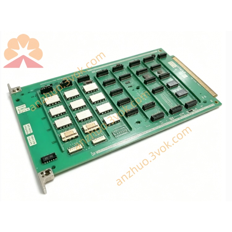
1.1 Product Overview
1.2 Key Features
Dual Analog + Digital Outputs: 2× analog (4–20 mA / 0–10 V) + 4× digital (24 V DC, 0.5 A) channels.
16-bit Resolution: ±0.1% full-scale accuracy for analog outputs.
Isolation & Protection: 1500 V DC isolation; overvoltage, overcurrent, short-circuit, and thermal protection.
Industrial Durability: -25°C to +60°C operation; DIN rail mount; compact rugged housing.
Software Configurable: Output type, range, fail-safe state, and filtering via PC software.
1.3 Specifications
Model: 1172C26
Manufacturer: Emerson Automation Solutions
Output Types:
Analog: 2 channels (4–20 mA, 0–10 V, software-selectable)
Digital: 4 channels (24 V DC, sinking/sourcing, 0.5 A max per channel)
Analog Resolution: 16-bit
Analog Accuracy: ±0.1% FS (25°C); ±0.2% FS (-25°C to +60°C)
Load Capacity:
Analog current (4–20 mA): ≤500 Ω
Analog voltage (0–10 V): ≥1 kΩ
Digital: 0.5 A @ 24 V DC per channel
Power Supply: 24 V DC ±10%, 200 mA (max)
Isolation: 1500 V DC (field side to logic/power)
Operating Temperature: -25°C to +60°C
Storage Temperature: -40°C to +85°C
Humidity: 5%–95% RH (non-condensing)
Dimensions: 120 mm × 80 mm × 25 mm
Weight: 360 g
2. Safety Precautions
Qualified Personnel Only: Installation, wiring, and service must be performed by trained, qualified technicians.
Power Off Before Wiring: Disconnect all power sources before connecting/disconnecting wires to avoid electric shock or equipment damage.
No Explosive/Corrosive Environments: Do not install in areas with flammable gases, vapors, or conductive dust.
Ventilation: Maintain ≥25 mm clearance on all sides for cooling; avoid blocking ventilation slots.
Cable Separation: Route signal cables separately from power cables to reduce EMI/RFI interference.
Proper Grounding: Connect the module’s protective earth (PE) terminal to a reliable low-resistance earth ground.
Overload Protection: Do not exceed rated output current/voltage; ensure external fuses or circuit breakers are used where required.
3. Installation
3.1 DIN Rail Mounting
Verify the DIN rail (35 mm) is clean, rigid, and securely mounted.
Align the module’s top mounting hooks with the upper edge of the rail.
Press the module downward until the bottom latch snaps onto the rail.
Gently tug the module to confirm it is firmly seated and cannot slide.
3.2 Terminal Assignment
| Terminal | Description |
|---|---|
| 1 | +24 V DC (Power Input) |
| 2 | 0 V DC (Power Common) |
| 3 | Analog Output 1 (+) |
| 4 | Analog Output 1 (–) |
| 5 | Analog Output 2 (+) |
| 6 | Analog Output 2 (–) |
| 7 | Digital Output 1 |
| 8 | Digital Output 2 |
| 9 | Digital Output 3 |
| 10 | Digital Output 4 |
| 11 | Digital Output Common (COM) |
| 12 | Protective Earth (PE / Ground) |
3.3 Wiring Procedure
Strip 6 mm of insulation from all cable ends.
Loosen terminal screws using a small Phillips screwdriver.
Insert each wire into its assigned terminal.
Tighten screws to 0.5–0.6 N·m torque (do not over-tighten).
Secure cables with cable ties to prevent mechanical strain on terminals.
For analog outputs: Use shielded twisted-pair cable; connect shield to PE at one end only.
For digital outputs: Use 22–24 AWG stranded copper wire.
4. Configuration
4.1 Software Connection
Connect the module’s RS-485 port to a PC using a USB-to-RS-485 adapter.
Install Emerson DeviceManager software (v5.0 or later) from the official website.
Launch DeviceManager; select “Scan for Devices” to detect the 1172C26.
Select the detected 1172C26 and click “Connect” (default address: 1; baud rate: 9600 bps).
4.2 Parameter Configuration
Analog Outputs (Channel 1 & 2):
Output Type: Select 4–20 mA or 0–10 V.
Range: Set engineering range (e.g., 0–100%, 0–50 bar, -20°C to +200°C).
Fail-Safe Value: Define output level on communication loss (e.g., 0%, 4 mA, 0 V, or last value).
Filter: Enable/disable low-pass filtering (0–100 Hz cutoff).
Digital Outputs (Channel 1–4):
Logic: Select Sinking (NPN) or Sourcing (PNP).
Fail-Safe State: Set ON or OFF on communication loss.
Pulse Mode: Enable/disable pulse output (pulse width: 10–1000 ms).
Communication:
Baud Rate: 9600 / 19200 / 38400 bps (default: 9600).
Data Bits: 8; Stop Bits: 1; Parity: None.
Slave Address: 1–247 (Modbus RTU).
4.3 Save & Apply
After setting all parameters, click Save to Device in DeviceManager.
Disconnect the USB-to-RS-485 adapter.
Power-cycle the module (remove and reapply 24 V DC) to activate the new configuration.
5. Operation
5.1 Power-Up Sequence
Apply 24 V DC power to terminals 1 (+24 V) and 2 (0 V).
POWER LED (green) illuminates steadily.
The module runs a 2-second self-diagnostic test.
Normal operation: STATUS LED flashes green (1 Hz).
Fault condition: STATUS LED flashes red (0.5 Hz); refer to Section 7.
5.2 Normal Operation
Analog Outputs: Convert controller commands (0–100%) to proportional 4–20 mA or 0–10 V signals to drive valves, actuators, or indicators.
Digital Outputs: Switch 24 V DC ON/OFF to control relays, contactors, solenoids, or lamps.
Communication: Communicates with the host controller via Modbus RTU over RS-485 (read/write output values, monitor status).
5.3 LED Status Indicators
POWER (Green):
ON: Power supply normal.
OFF: No 24 V DC power or power supply fault.
STATUS (Green/Red):
Flashing Green (1 Hz): Normal operation, no faults.
Flashing Red (0.5 Hz): Fault detected (overload, short circuit, communication loss, or self-test failure).
Solid Red: Critical fault (hardware damage; replace module).
6. Maintenance
Monthly Inspection: Check LED status; verify no loose wires or damaged cables.
6-Month Maintenance:
Tighten terminal screws to 0.5–0.6 N·m.
Clean module surface with a dry lint-free cloth (no liquids or solvents).
Inspect for corrosion or overheating signs (discoloration).
Firmware Updates: Check Emerson’s website for latest firmware; update via DeviceManager.
Replacement: If faulty, replace with the same model (1172C26) and reconfigure parameters.
7. Troubleshooting
| Issue | Possible Cause | Solution |
|---|---|---|
| POWER LED OFF | No 24 V DC supply; reversed polarity; blown fuse | Check power source/wiring; verify polarity; replace external fuse |
| STATUS LED FLASHES RED | Overload/short circuit on output; communication loss; self-test failure | Disconnect field devices; check wiring/load; verify controller communication; power-cycle module |
| Analog Output Incorrect | Wrong output type/range; loose wire; excessive load resistance | Reconfigure analog settings; tighten terminals; reduce load resistance (≤500 Ω for mA; ≥1 kΩ for V) |
| Digital Output Not Switching | Wrong logic (sinking/sourcing); loose wire; overload | Reconfigure digital logic; tighten terminals; reduce load current (≤0.5 A) |
| RS-485 Communication Failure | Incorrect baud rate/address; reversed A/B wires; termination missing | Match controller settings; swap A/B wires; add 120 Ω termination resistor at bus ends |
8. Ordering Information
Model: 1172C26
Accessories:
USB-to-RS-485 adapter (for configuration)
35 mm DIN rail (1 m length)
Shielded twisted-pair cable (analog)
Replacement Parts: Terminal block assembly, status LED assembly
Get a Quote