
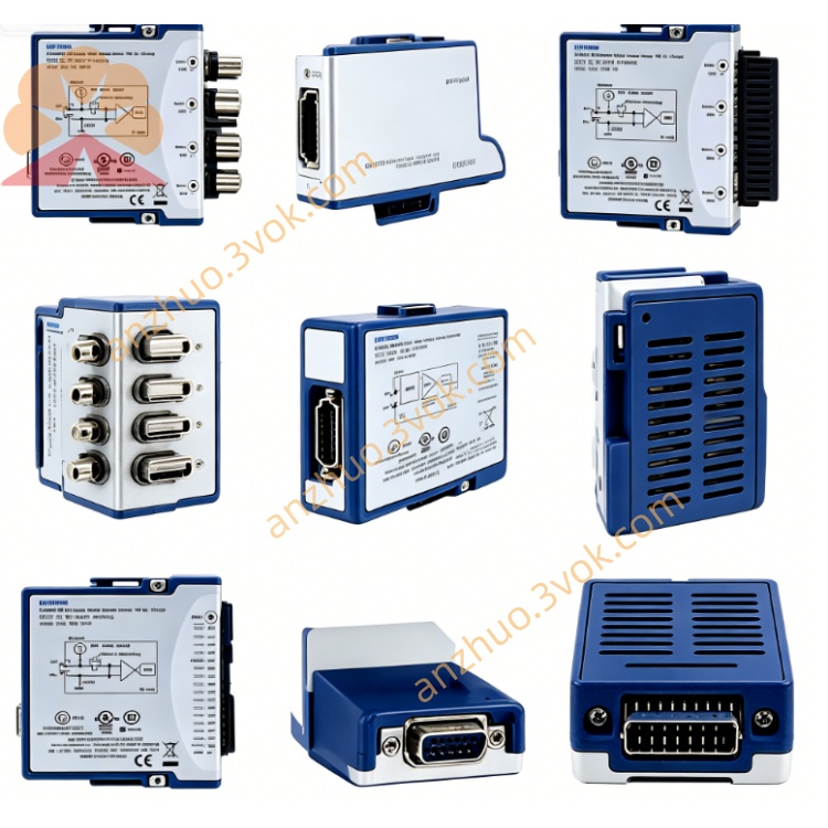
NI PXIe-6528 Isolated Industrial Digital I/O Module
The PXIe-6528 (often referred to as PXI-6528, part number 778543-01) is an industrial-grade isolated digital I/O module from National Instruments (NI), with a 3U PXI specification. It offers 24 optical isolation inputs + 24 solid-state relays outputs. The channels are fully electrically isolated from each other, with a withstand voltage of up to 500 Vrms. It can directly connect to ±60 V industrial signals and is equipped with a built-in watchdog and programmable power-on status, making it suitable for industrial control and testing scenarios with strong interference and high reliability.
Description
Model Definition
PXIe stands for PXI Express modular instrument bus, and this module is fully compatible with standard PXI chassis. The model number 6528 represents an isolated digital I/O module with 24 input channels and 24 output channels. This device adopts optocoupler isolation and solid-state relay output design, targeting industrial-grade signal switching and collection applications.
Key Specifications
Digital input section includes 24 channels with optical isolation between every channel. The working voltage range is ±60 V DC, and the maximum input current per channel is 3 mA. The isolation voltage reaches 500 Vrms between channels and between channel and ground. It supports programmable digital filter for signal debouncing, and can detect signal changes with a minimum pulse width of 150 microseconds.
Digital output section has 24 solid-state relay channels in normally open type. The applicable voltage covers ±60 V DC and 0 to 30 V AC. Each channel can provide a maximum driving current of 150 mA, with typical on-resistance of 0.2 ohm. The isolation performance is consistent with input channels at 500 Vrms. The module is built with a hardware watchdog function and allows users to set fixed output states when powered on.
For general electrical and environmental parameters, the total power consumption is approximately 32 W. The standard operating temperature ranges from 0 °C to 55 °C. The module is designed as single-slot 3U form factor with compact structure.
Interface and Communication Configuration
The module communicates with the host via standard PXI bus, supporting plug-and-play, DMA data transmission and RTSI synchronization function. All digital input and output signals are led out through a single 68-pin VHDCI connector on the front panel. It can work with PXI trigger bus to realize signal triggering and synchronous linkage with other PXI modules. The supporting driver is NI-DAQmx, which can run on Windows and real-time operating systems, and supports secondary development with mainstream programming languages.
Core Functions
Full-channel electrical isolation effectively eliminates ground loop interference and protects internal circuits from high-voltage spikes. The wide voltage input and output capability enables direct connection with common industrial switching signals, relays and solenoid valves. The programmable power-up state prevents unexpected actions of external devices during system startup. The hardware watchdog will automatically switch outputs to safe states once the system runs abnormally. Built-in digital filter and signal change detection reduce signal jitter and lower system resource occupancy. High channel density integrates 48 isolated I/O channels in one slot to save chassis space and system cost.
Application Scenarios
It is applied to industrial automation production lines for signal collection of switching states and drive control of actuators such as solenoid valves and contactors. In automotive electronic testing, it simulates switching signals of electronic control units and completes load drive tests. For power and energy industry, it monitors the state of high-voltage switches and performs aging tests on relays and contactors. It is also used in aerospace and military test systems to collect and control digital signals under strong interference. Besides, it can serve for equipment status monitoring and safety interlock control of mechanical devices.
Usage and Maintenance Instructions
Operation Guidelines
Install the module into a free slot of 3U PXI or PXIe chassis and fasten the screws. Use shielded cables for signal wiring, and separate strong electricity cables from weak electricity cables. Set power-up output status, watchdog timeout and filter parameters through configuration software. Do not apply voltage exceeding 500 Vrms between channels or to ground to avoid damage to isolation components.
Maintenance Instructions
Wipe the front panel and connectors regularly with dry soft cloth to remove dust and keep good contact. This digital I/O module does not require regular calibration. Inspect isolation performance and on-state resistance of output channels every two years. When the module is not in use, store it in a dry and cool environment and take anti-static measures. If abnormal operation occurs, check wiring, power supply and function configuration first, and inspect load status when output channels work improperly.
Get a Quote