
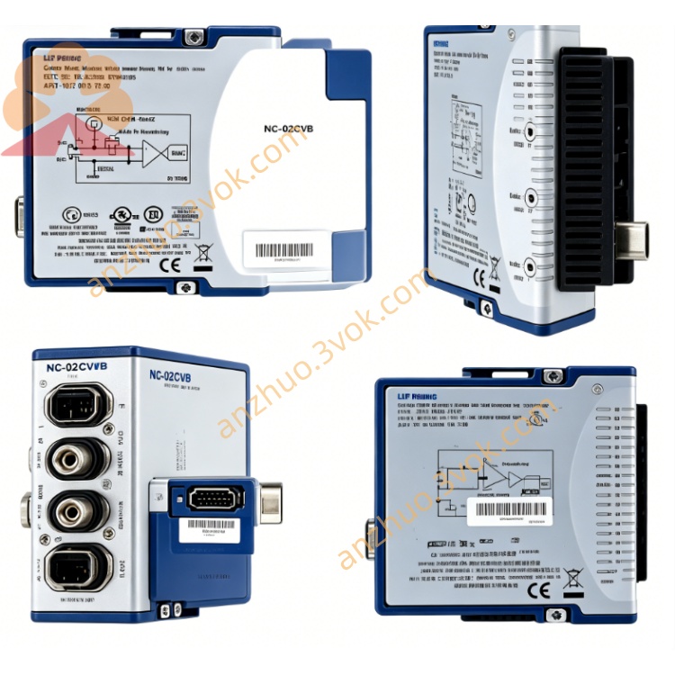
NI PXIe-5663E 6.6GHz RF Vector Signal Analyzer
The PXIe‑5663E is a modular 6.6 GHz PXI Express Vector Signal Analyzer (VSA) by National Instruments, composed of three separate PXIe modules: PXIe‑5601 (RF Downconverter), PXIe‑5622 (IF Digitizer), and PXIe‑5652 (LO Source)NI. It delivers wide instantaneous bandwidth, high dynamic range, and fast measurement speed for RF/communications test, serving as both a spectrum analyzer and vector signal analyzer.
Description
Model Nomenclature
PXIe represents the PXI Express high-speed modular instrumentation bus. The number 56 stands for the NI PXI series of RF and intermediate frequency test instruments. 63 indicates a vector signal analyzer with 6.6 GHz frequency range. The letter E refers to the enhanced version with upgraded overall performance.
Technical Specifications
This integrated system covers a frequency range from 10 megahertz to 6.6 gigahertz, and its maximum instantaneous analysis bandwidth reaches 50 megahertz at three decibels attenuation. The typical noise floor is lower than minus 158 dBm per hertz at 1 gigahertz carrier frequency. The typical spurious-free dynamic range is 80 decibels, and the typical third-order intercept point is positive 21 dBm.
The built-in IF digitizer adopts 16-bit high-resolution design, and provides two onboard memory options of 64 megabytes and 256 megabytes. The main signal input interface is SMA connector with 50 ohm nominal impedance. It supports both internal oven-controlled crystal oscillator and external 10 megahertz reference clock input. The system is equipped with PXI trigger bus and external trigger interface for synchronous control. The operating temperature ranges from 0 degrees Celsius to 55 degrees Celsius, and the storage temperature ranges from minus 40 degrees Celsius to 70 degrees Celsius. The recommended calibration cycle is two years.
Interface and Communication Configuration
The whole system adopts standard PXIe bus architecture and supports high-speed data transmission. The matched drivers include NI-RFSA and NI-RFmx, and it is also compatible with IVI-COM standard drivers. Users can complete hardware recognition, parameter configuration and fault diagnosis through NI-MAX software. Secondary development and automated test control can be realized by using LabVIEW, C, C++, Python and .NET programming environments.
It supports PXI trigger bus and NI-TClk synchronization technology to achieve high-precision timing alignment with other PXIe modular instruments. Internal inter-module connection adopts dedicated coaxial cables to transmit local oscillator signals and intermediate frequency signals stably. The system reserves external 10 megahertz reference clock interface to realize unified clock synchronization of the whole test platform.
Core Features
Adopting modular combination design, the system integrates downconversion, digital acquisition and local oscillator signal generation functions, which is easy for system deployment and function expansion. The 50 megahertz wide instantaneous bandwidth can capture and analyze various high-speed wideband wireless signals. It maintains high sensitivity and linearity, ensuring reliable measurement results for both weak signals and large-amplitude signals.
It supports RF list mode, which realizes rapid frequency switching and parameter configuration, effectively improving the test efficiency for mass production. Based on software-defined technology, it can switch between spectrum analysis and vector signal analysis functions flexibly. It is compatible with multiple mainstream communication standards, and can complete modulation analysis and performance testing for different wireless devices.
Application Scenarios
It is used for research and development verification and production testing of wireless communication terminals and modules supporting LTE, Wi-Fi, Bluetooth and IoT protocols. It conducts performance characterization for RF components such as power amplifiers, filters and mixers. It is applicable to spectrum monitoring, signal capturing and interference analysis in electronic warfare scenarios.
It serves as the core test equipment for performance verification of radio frequency integrated circuits and system-on-chips in semiconductor industry. In aerospace and defense fields, it completes radar signal analysis, signal intelligence collection and related system performance evaluation.
Usage and Maintenance Instructions
Installation and Configuration
Install the three supporting modules of the system into adjacent slots of a 3U PXIe chassis and fasten the front panel latches. Use dedicated coaxial cables to connect the local oscillator output port to the downconverter input port, and connect the intermediate frequency output of the downconverter to the digitizer. Connect the device under test to the main RF input port, and access the external 10 megahertz reference clock if system synchronization is required. Power on the chassis, and the software will automatically identify all modules. Set frequency range, bandwidth, power level and trigger parameters according to test requirements before formal measurement.
Operation Guidelines
Keep the whole system powered on for 30 minutes to finish warm-up before conducting high-precision measurement tasks. Do not feed input signals exceeding positive 10 dBm into the RF input port to avoid permanent damage to the front-end circuit. Make full use of the list mode function when performing batch frequency point tests to optimize test speed. Enable unified trigger and clock functions when working with other PXIe instruments to guarantee synchronization accuracy.
Daily Maintenance
Keep all modules, connecting cables and connectors clean, dry and well ventilated during operation. Tighten SMA connectors gently during plugging and unplugging to prevent deformation or damage of internal pins. Inspect cables and connection status regularly every month to eliminate hidden troubles such as aging and poor contact. Perform professional overall calibration every two years to maintain long-term measurement accuracy. Disconnect all cables and place the system in an electrostatic protective environment for storage when it is not in use.
Get a Quote