
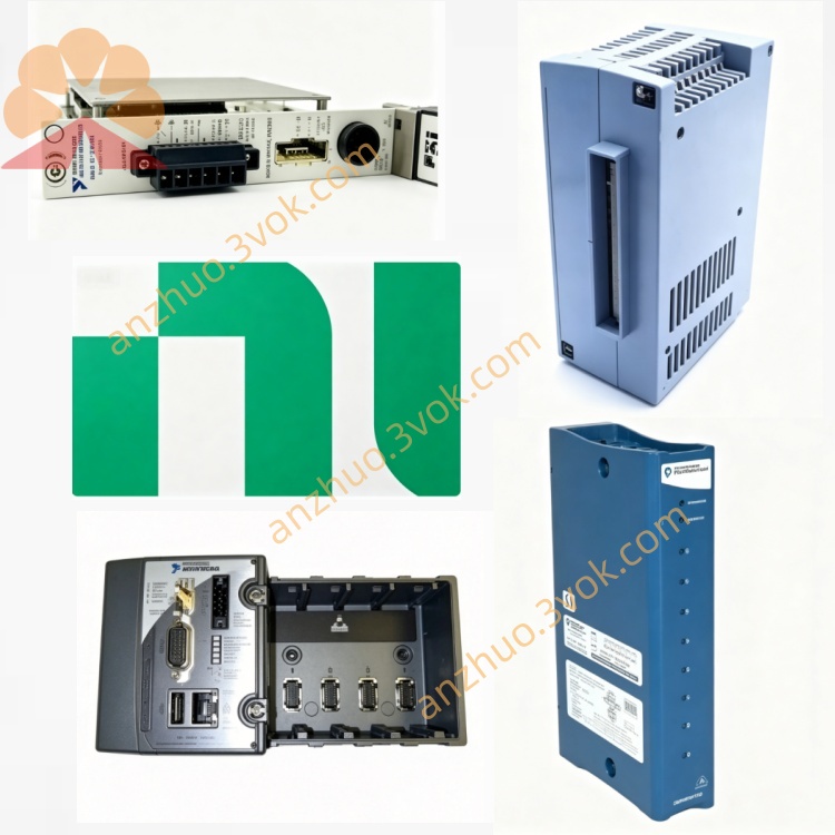
NI PXIe-5630 6GHz 2-Port RF Vector Network Analyzer
Description
Model Nomenclature
PXIe: PXI Express high‑speed modular instrumentation bus.
56: NI PXI RF and IF test instrument series.
30: 2‑port, 6 GHz, two‑slot vector network analyzer supporting T/R (transmission/reflection) and full S‑parameter vector analysis.
Technical Specifications
Form Factor: 3U two‑slot PXIe module.
Ports: 2 (PORT1/PORT2, 50 Ω, K‑type connectors).
Frequency Range: 10 MHz to 6 GHz; 10 Hz resolution.
Dynamic Range: >110 dB (typical).
Noise Floor: <‑123 dBm/Hz.
Source Power: ‑30 dBm to +5 dBm; 0.5 dB step.
Sweep Speed: <400 μs/point (3,201 points).
IF Bandwidth: 10 Hz to 30 kHz.
Reference Clock: External 10 MHz (SMA); internal optional.
Trigger: PFI 0 (SMA, 3.3 V TTL).
Operating Temperature: 0 °C to 55 °C; Storage: ‑40 °C to 70 °C.
Interface and Communication Configuration
Bus: PXIe Gen1 x1, supporting high‑speed DMA and peer‑to‑peer data streaming.
Drivers: NI‑VNA, IVI‑COM; compatible with LabVIEW, C/C++, Python, .NET.
Software: NI‑MAX (configuration/calibration), NI‑VNA Soft Front Panel (interactive control).
Synchronization: PXI trigger bus, star trigger, NI‑TClk for multi‑module phase synchronization.
Calibration: Supports SOLT, TRL, automatic precision calibration, and reference plane extension.
Core Features
Full Vector S‑Parameter Measurement: Precise S11 (reflection) and S21 (transmission) measurement with amplitude, phase, and impedance data.
Wide Dynamic Range and Low Noise: Enables stable and reliable measurement of weak signals and high‑isolation devices.
Fast Sweep Speed: Maximizes production throughput, suitable for parallel testing of multiple DUTs.
Automated Precision Calibration: Built‑in calibration routines reduce manual errors and ensure long‑term accuracy.
Modular Integration: Seamlessly integrates with PXIe‑5622, PXIe‑5653, and other NI RF instruments to form a unified test system.
Application Scenarios
RF Component Test: S‑parameter and linear characterization of filters, amplifiers, mixers, antennas, cables, and connectors.
Wireless Communication: R&D and production test of 5G/6G front‑end modules, transceivers, and MIMO components.
Aerospace and Defense: Phase/amplitude consistency test of radar components, RF links, and electronic warfare modules.
Semiconductor Test: Impedance matching and insertion loss characterization of RF chips, packages, and substrates.
General‑Purpose Test: Dielectric constant measurement of materials, signal integrity analysis, and RF system integration validation.
Get a Quote