
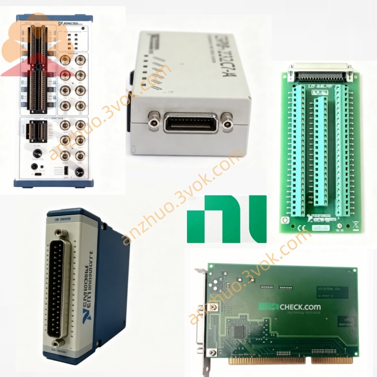
NI PXIe-5622 150MS/s 16Bit IF Digitizer Module
The PXIe-5622 is a 3U single-slot PXI Express intermediate frequency digitizer designed for RF and wireless test applications. It features 16-bit resolution, a maximum real-time sampling rate of 150 MS/s and 250 MHz analog bandwidth. Integrated with FPGA-based onboard signal processing and large onboard memory, this module can work independently for IF signal acquisition, or cooperate with down-converters to build a complete RF signal analyzer system. It delivers excellent dynamic range and stable performance, and is widely adopted in communication, radar, aerospace and semiconductor test fields.
Description
Model Nomenclature
PXIe refers to the PXI Express high-speed modular instrumentation bus. The number 56 stands for NI PXI RF and IF test instrument series. 5622 represents a single-channel 16-bit IF digitizer with 150 MS/s sampling rate and 250 MHz bandwidth, equipped with onboard processing and large memory for IF signal capture and spectrum measurement.
Technical Specifications
This module adopts a 3U single-slot mechanical form factor and provides one single-ended analog input channel with 50 ohm nominal input impedance. It has 16-bit vertical resolution and supports a maximum real-time sampling rate of 150 MS/s. The analog bandwidth covers 3 megahertz to 250 megahertz for the direct path, and it also provides a 50 megahertz anti-aliasing IF bandwidth centered at 187 megahertz.
The full-scale input power is +4 dBm, while the maximum safe input power is limited to +20 dBm to protect the front-end circuit. Two onboard memory configurations are available, including 64 megabytes and 256 megabytes. The typical spurious-free dynamic range is better than -76 dBc. Built-in onboard processing functions include digital down conversion, fractional resampling, numerically controlled oscillator, digital gain and offset adjustment, as well as self-calibration.
It supports NI-TClk synchronization, PXI trigger bus and star trigger. The internal clock is a 150 megahertz voltage controlled crystal oscillator, and an external 100 megahertz reference clock input is provided via SMA connector. The operating temperature ranges from 0 degrees Celsius to 55 degrees Celsius, and the storage temperature ranges from minus 40 degrees Celsius to 70 degrees Celsius. Front panel interfaces include SMA ports for IF input and clock input, as well as PFI lines for auxiliary triggering.
Interface and Communication Configuration
The module uses PXIe Gen1 x1 bus and supports high-speed direct memory access data streaming for long-duration data recording at full sampling rate. It is compatible with NI-SCOPE, NI-DAQmx and IVI-COM drivers for Windows operating systems.
Users can complete hardware configuration, status monitoring and fault diagnosis through NI-MAX. Secondary development and automated test control can be implemented based on LabVIEW, C, C++, Python and .NET. It supports NI-TClk technology to achieve picosecond-level timing alignment with other PXIe RF instruments. The module also supports peer-to-peer data transmission between different modules to reduce system load.
Core Features
The combination of 16-bit high resolution and wide dynamic range enables accurate acquisition of weak IF signals and high-precision spectrum analysis. The 150 MS/s sampling rate and 250 MHz wide bandwidth cover mainstream frequency bands of communication and radar intermediate frequency signals, supporting wideband signal capture.
FPGA-powered onboard signal processing realizes real-time digital down conversion, resampling and frequency shifting, which greatly reduces computing pressure on the host computer and improves overall measurement efficiency. Large-capacity onboard memory supports long waveform acquisition and multi-segment recording, avoiding frequent data interaction with the host.
High-precision synchronization capability ensures phase coherence among multiple modules, which meets the test requirements of MIMO systems and phased array radar. With standard PXIe architecture and rich interfaces, it can be easily integrated into various RF test platforms and combined with other NI RF modules to form a complete signal analysis system.
Application Scenarios
It is applied to IF signal collection, spectrum monitoring and transceiver performance testing for 5G and 6G wireless communication equipment and MIMO systems. In aerospace and defense industries, it captures radar pulse and chirp signals, analyzes electronic warfare signals, and conducts performance tests for satellite communication receivers.
It acts as the core IF acquisition unit of PXI RF signal analyzers and works with down-converters to complete RF signal measurement. It is also used for performance verification and nonlinear characteristic analysis of RF chips, mixers and amplifiers in semiconductor testing. In addition, it can be used for high-frequency signal measurement in ultrasonic detection, vibration analysis and scientific research.
Usage and Maintenance Instructions
Installation and Configuration
Insert the module into an empty 3U slot of the PXIe chassis and fasten the front panel latch. Connect the IF input port to a down-converter or signal source with SMA cables, and connect the external reference clock if needed. Power on the chassis, and the system will automatically recognize the module. Open NI-MAX to set sampling rate, input range, filter parameters, clock source, trigger mode and onboard processing parameters before starting measurement tasks.
Operation
Allow a 15-minute warm-up period before performing high-precision measurements. Never feed input signals exceeding +20 dBm to prevent permanent damage to the front-end circuit. Select appropriate filters and digital down conversion configurations according to actual signal characteristics to optimize signal-to-noise ratio. Enable direct memory access streaming mode during long-time continuous acquisition to ensure complete data recording.
Daily Maintenance
Keep the module, connecting cables and connectors clean, dry and well ventilated during operation. Do not apply excessive force when tightening SMA connectors to avoid damaging internal pins. Inspect cables and connections regularly to check for aging and poor contact. Run built-in self-calibration every month to compensate for parameter drift, and perform professional external calibration every two years to maintain long-term measurement accuracy. Disconnect all cables and store the module in an electrostatic protected environment when it is not in use.
Get a Quote