
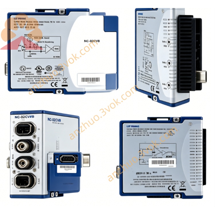
NI PXIe-2543 6.6GHz Dual 4×1 Solid-State RF Mux Module
Description
Model Nomenclature
PXIe: PXI Express high‑speed modular instrumentation bus
25: NI switch/matrix product series
43: Dual 4×1 solid‑state RF multiplexer, 6.6 GHz, SMA connectors, 50 Ω, fully terminated
Technical Specifications
Form factor: 3U, 1‑slot PXIe (hybrid/peripheral slot)
Topology: Dual 4×1 (SP4T) multiplexers (Bank A + Bank B), independent operationNI
Impedance: 50 Ω (all ports)
Frequency range: 10 MHz to 6.6 GHz
Relay type: Solid‑state FET, non‑mechanical
Switching speed: ≤76 μs (trigger‑in to stable output)
Relay life: Unlimited (no mechanical wear)
Insertion loss: Typical <3.5 dB, max 6.1 dB @ 6.6 GHz
Isolation: >60 dB @ 6.6 GHz
Return loss: >15 dB (all terminated channels)
RF power handling: +30 dBm (chassis on), +20 dBm (chassis off)
Maximum DC voltage: ±8 V
Trigger pulse width: 150 ns (minimum detectable)
Operating temperature: 0 °C to 55 °C; storage: −20 °C to 70 °C
Power consumption: 0.4 W @ 12 V, 1 W @ 3.3 V (PXIe)
Dimensions: 21.6 × 2.0 × 13.0 cm; weight: ~775 g
Interface and Communication Configuration
Front‑panel I/O: 10×SMA female connectors (4 CH A + 4 CH B + 2 COM) + 2×SMB female triggers (TRIG IN/OUT)
Bus: PXIe Gen1, plug‑and‑play
Triggering: PXI trigger lines + front‑panel SMB triggers for multi‑module synchronization
Software support: NI‑MAX for configuration; LabVIEW, LabWindows/CVI, C++ APIs with NI‑SWITCH driver
Compatibility: Windows OS, 3U PXIe chassis
Core Features
Solid‑state reliability: FET relays eliminate mechanical wear, providing unlimited lifecycle and stable performance in 24/7 production environments.
Dual independent banks: Two 4×1 multiplexers enable parallel routing for multi‑site testing, doubling throughputNI.
Full termination: Every channel and common line is 50 Ω terminated, minimizing reflections and ensuring excellent RF signal integrity.
Ultra‑fast switching: 76 μs switching speed accelerates test cycles, ideal for high‑volume manufacturing.
High power handling: Supports up to +30 dBm continuous RF power for robust signal routing.
SMA connectivity: Industry‑standard SMA connectors deliver reliable, high‑frequency connections up to 6.6 GHz.
Application Scenarios
Semiconductor test: RF parametric and functional testing of transistors, amplifiers, and ICs up to 6.6 GHz.
Wireless device testing: High‑speed routing for 5G, Wi‑Fi, and Bluetooth modules in mass production.
Microwave system calibration: Switching between reference signals and DUTs in radar and communication test benches.
Multi‑site ATE: Parallel testing of multiple DUTs to maximize throughput in manufacturing lines.
General‑purpose RF switching: High‑frequency signal routing between signal generators, analyzers, and oscilloscopes.
Get a Quote