
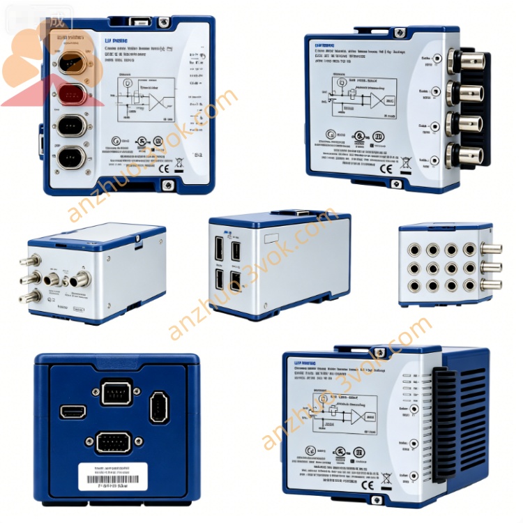
NI PXIe-2529 128-Crosspoint 2-Wire Matrix Switch Module
Description
Model Nomenclature
PXIe: PXI Express bus
25: Switch/matrix series
29: 128‑crosspoint, 2‑wire, 150 V / 1 A matrix with latching relaysNI
Technical Specifications
Form factor: 3U, 1‑slot PXIeNI
Matrix size: 128 crosspoints, 2‑wire
Configurations: 4×32 or 8×16 (via terminal blocks)NI
Relay type: Electromechanical, latching; Ag–Pd–Au contactsNI
Max switching voltage: 150 VDCNI
Max switching current: 1 A DCNI
Bandwidth: 10 MHz
Scan rate: 120 cycles/sNI
On‑resistance: Typical <1.5 Ω
Relay life: >10⁶ operations (rated)
Operating temp: 0 °C to 55 °C; storage: −20 °C to 70 °CNI
Power: 7.5 W (+12 V), 2.5 W (+3.3 V)NI
Dimensions: 21.6 × 2.0 × 13.0 cm; weight: 410 gNI
Interface and Communication
Front panel: 100‑pin HDI connector for matrix I/ONI
Bus: PXIe Gen1, triggers 0–7 for multi‑module syncNI
Trigger: Hardware input, min pulse width 150 ns
Software: NI‑MAX configurable; LabVIEW/CVI/C++ APIs; NI‑SWITCH / Switch Executive supportedNI
Core Features
High‑density matrix: 128 crosspoints in one slot, 2‑wire for precision resistance/voltage measurementsNI
Dual topology: Software/accessory selectable 4×32 or 8×16NI
Low thermal offset: Gold‑alloy contacts minimize drift in low‑level DC measurementsNI
Latching relays: Lower power, stable state after triggerNI
Relay health monitoring: Onboard counter for predictive maintenanceNI
Deterministic scanning: Hardware triggers ensure repeatable timingNI
Application Scenarios
Semiconductor parametric test (low‑voltage, high‑channel count)
Aerospace/defense subsystem signal routing
Industrial sensor and low‑power device validation
Automotive ECU and distributed I/O testing
Precision 2‑wire resistance/multiplexing systems
Get a Quote