
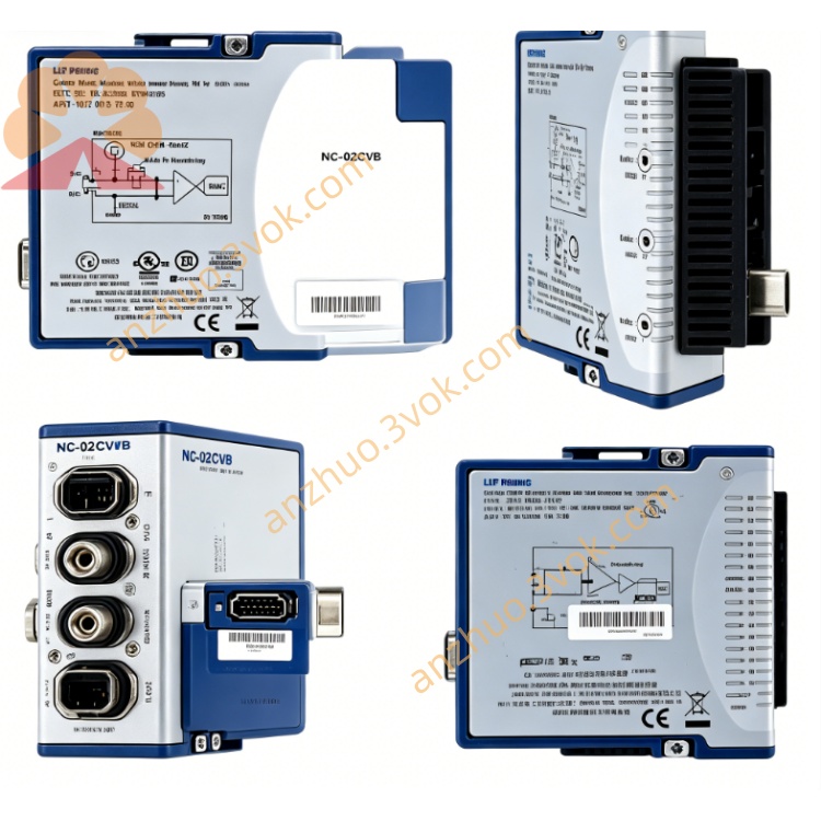
NI PXIe-2512 8CH Fault Insertion Switch Module
he PXIe-2512 (NI Part Number: 780587-12) is a 7-channel high-power fault insertion unit (FIU) designed by National Instruments for PXI Express systems. As a 3U two-slot PXIe module, it integrates FET relays to deliver robust signal switching and fault simulation capabilities. It supports feedthrough channels that remain transparent when closed, enabling simulation of open circuits, pin-to-pin shorts, shorts to battery, and shorts to ground on a per-channel basis. With a maximum switching voltage of 50 VDC, 10 A continuous current, and 800 kHz bandwidth, it is optimized for hardware-in-the-loop (HIL) simulation, electronic reliability testing, and control system validation.
Description
Model Nomenclature
PXIe:Stands for PXI Express, denoting compliance with the high-speed PXI modular instrumentation bus standard.2512:The specific model identifier for this 7-channel fault insertion switch series. The "25" prefix indicates a switch module, while "12" denotes a high-power FIU configuration with 10 A current rating and fault bus support.
Technical Specifications
The module adopts a 3U two-slot PXIe form factor, measuring 21.6 cm × 4.1 cm × 13.0 cm and weighing 403 g. It provides 7 independent feedthrough channels with FET relays, offering a typical DC path resistance of 16 mΩ. The maximum switching voltage is 50 VDC or 30 V ACrms, with a continuous current rating of 10 A per channel and a pulsed current capacity of 50 A for up to 600 μs. The switching bandwidth exceeds 800 kHz in a 50 Ω system. Relay actuation time is 8 μs typical (35 μs maximum), with unlimited operational life under rated conditions. It features overcurrent detection at 10.5 A with 20 ms delay and overtemperature protection. Operating temperature ranges from 0 °C to 50 °C, storage temperature from -40 °C to 70 °C, and relative humidity from 5% to 85% noncondensing. Power consumption is 14.7 W (+12 V) and 1.4 W (3.3 V) via PXIe bus.
Interface and Communication Configuration
The front panel is equipped with two 8-position male DSUB connectors for signal I/O, providing access to the 7 channels and fault buses. It supports PXIe Gen1 bus communication and PXI trigger lines <0...7> for multi-module synchronization, with a minimum input trigger pulse width of 150 ns and programmable output trigger pulse widths from 1 μs to 62 μs. The module is plug-and-play compatible with Windows operating systems, configurable via NI-MAX, and programmable through LabVIEW, LabWindows/CVI, and C++ APIs. It supports external fault bus connections for battery and ground fault simulation.
Core Features
It enables independent fault simulation per channel, including open circuits, pin-to-pin shorts, shorts to battery voltage, and shorts to ground. The 10 A continuous current and 50 A pulsed current ratings support high-power signal switching for automotive and industrial applications. FET relays provide fast switching speed and long service life. Integrated overcurrent and overtemperature protection ensures safe operation under fault conditions. The feedthrough design maintains signal integrity in normal operation while allowing fault injection on demand. It seamlessly integrates with PXIe HIL systems for real-time control system validation.
Application Scenarios
It is widely used in automotive ECU and FADEC validation for simulating wiring harness faults. It serves electronic reliability testing for aerospace and defense systems. It supports HIL simulation for industrial control systems and power electronics. It performs fault injection testing for avionics and military hardware. It is applied in automotive battery management system (BMS) testing and power distribution network validation.
Usage and Maintenance Instructions
Installation and Configuration
Insert the module into any 3U two-slot PXIe chassis and secure the front panel latch. Connect signal lines to the DSUB connectors, ensuring correct channel mapping for DUT and fault bus connections. Power on the PXIe chassis; the system will automatically detect the module. Launch NI-MAX to configure channel parameters, fault bus assignments, and trigger settings. Develop test programs using LabVIEW or other supported environments to implement fault injection sequences. Verify all connections before applying power to avoid short circuits.
Daily Maintenance
Keep the module and chassis in a clean, dry, and well-ventilated environment within the rated temperature range. Avoid excessive force when connecting DSUB cables to prevent connector damage. Inspect cables and connectors periodically for wear or loose connections. Ensure the chassis has adequate cooling to prevent overtemperature conditions. Store the module in a dry, antistatic environment when not in use.
Safety Notice
Do not apply voltages exceeding 50 VDC or 30 V ACrms to avoid permanent damage. Adhere to electrostatic discharge (ESD) guidelines when handling the module. Disconnect all power sources before installing, removing, or servicing the module. Do not operate the module with open or damaged connectors. Dispose of the module in accordance with local electronic waste regulations at end-of-life.
Get a Quote