
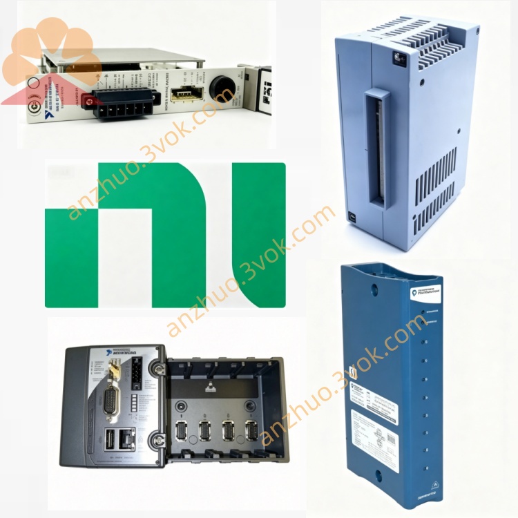
NI PXI-7344 4-Axis Stepper & Servo Motion Controller
Description
II. Model Interpretation
PXI: Standard 3U single slot, compatible with PXI/PXIe mixed slots, supports PXI trigger bus and RTSI real-time synchronization bus.
7344: 73xx motion control series, 4 represents 4 axes, 4 represents enhanced (Enhanced), compared to 7340, it improves control cycle, interpolation accuracy and program execution capability.
Positioning: 4-axis high-performance servo/stepper enhanced motion control card, suitable for complex trajectories, high-speed linkage and nanosecond-level synchronization scenarios.
III. Technical Parameters (25℃)
1. Motion Control Core
Control Axis Number: 4 axes independent/synchronous, servo (brushed/brushless), stepper motor compatible.
Control Cycle: 62 μs/axis (improved compared to 7340), total 4-axis cycle 250 μs.
Position Range: ±2³¹ counts (servo)/±2³¹ steps (stepper).
Speed: servo 20 M counts/second; stepper 4 M steps/second.
Acceleration: servo 244~512 M counts/second²; stepper 2.44~512 M steps/second².
Control Modes: PID/PIVff/double loop control/S-curve, supports electronic gearing, 3D straight line/arc interpolation.
2. Analog I/O
Analog Output (AO): 4 channels ±10 V, 16 bits, servo command output.
Analog Input (AI): 8 channels ±10 V, 16 bits, sensor/feedback acquisition.
3. Encoder and Feedback
Encoder Interface: 4 channels A/B/Z phases, up to 4 MHz, supports incremental encoders.
Feedback Type: encoder, analog quantity, pulse command, supports double-loop feedback.
4. Digital I/O
Channels: 32 TTL, bidirectional configurable, 16 input/16 output each.
Level: high ≥ 2.4 V, low ≤ 0.4 V, maximum pull/hold current 8 mA.
5. Physical and Environmental
Connector: 2×68-pin VHDCI (motion I/O + digital I/O).
Power Supply: PXI backplane + 5 V/+12 V/-12 V, power consumption approximately 18 W.
Operating Temperature: 0 ℃ ~ 55 ℃.
Storage Temperature: -20 ℃ ~ 70 ℃.
IV. Interface and Communication Configuration
1. Hardware Interface
Motion I/O (68-pin): 4 channels encoders, 4 channels AO, 8 channels AI, limit/origin, break point input.
Digital I/O (68-pin): 32 TTL, used for triggering, interlock, status monitoring.
Backplane: PXI trigger bus (8 channels), RTSI bus, multi-module synchronization accuracy **<100 ns**.
2. Software and Drivers
Driver: NI-Motion, supports complex interpolation, electronic gearing, fly saw, contour control.
Development Environment: LabVIEW, C/C++, Python, TestStand, supports real-time control.
Functions: On-board multi-task (10 programs), hardware breakpoints (200 ns), watchdog (63 ms), fault-safe shutdown.
V. Core Functions
Enhanced 4-axis closed-loop control, 62 μs high-speed update
Each axis 62 μs PID update (better than 7340's 62.5 μs), supports servo/stepper mixed control; RTSI bus synchronization, multi-axis timing jitter **<100 ns**.
On-board real-time multi-task and complex trajectory interpolation Dual processors + real-time OS, capable of running 10 motion programs simultaneously; natively supports 3D linear/arc interpolation, contour control, and electronic gearing, without occupying the host CPU.
Rich I/O integration, integrated control
4 channels of 16-bit AO, 8 channels of 16-bit AI, 32 channels of TTL I/O, 4 channels of encoders, directly connect to motors, sensors, limit switches, simplifying the system architecture.
Advanced control algorithms and safety protection
PID + feedforward control, S-curve acceleration/deceleration smoothness; hardware limit, software limit, watchdog, short circuit protection, automatic safe shutdown in case of faults.
System-level synchronization and integration
Share the clock and trigger with PXI data acquisition, vision, and FPGA modules to build a unified time reference, suitable for complex automation system integration.
Six. Application scenarios
Precision processing and manufacturing
Laser cutting, CNC precise positioning, semiconductor wafer handling, PCB drilling, complex trajectories and micrometer-level positioning requirements.
Automation testing and verification
Multi-axis motion platform testing, sensor calibration, product lifespan testing, robot joint performance verification, high-speed dynamic response scenarios.
High-speed precise positioning system
Electronic manufacturing assembly machines, optical platforms, biological 3D printing, high-speed sorting machines, high dynamic response and complex motion trajectory requirements.
Servo/stepper motor control
Industrial robots, CNC machines, packaging machinery, textile equipment, multi-axis synchronous and联动 control.
Research and laboratory automation
Optical instruments, precision measurement equipment, automated experimental platforms, nanosecond-level synchronization and high-precision motion control.
Seven. Installation and Maintenance Instructions
1. Installation and Power On
Disconnect power, insert into any slot of the PXI chassis, tighten screws and reliably ground; before powering on, check that the 68-pin cable has no short circuit / false connection to avoid damaging the I/O channels. Keep the chassis ventilated during operation, with an ambient temperature of ≤55℃ to avoid temperature accumulation affecting control accuracy.
2. Wiring and Operation
Cables: Use shielded 68-pin VHDCI cables, separate analog signals, encoder signals, and digital signals for wiring to reduce crosstalk; encoder cable length ≤10 m to avoid signal attenuation.
Configuration: Set the axis type (servo/stepper), control mode, limit parameters, trajectory data in the software; for the first run, perform no-load debugging first, confirm normal motion before connecting the load.
Synchronization: When synchronizing multiple cards, use PXI_TRIG or RTSI signals to ensure consistent timing; the hardware breakpoint is used for precise triggering of external events.
3. Daily Maintenance
Regularly clean the 68-pin connectors, check the integrity of the cable shielding layer, add a dust cap for long-term storage to prevent oxidation and dust from affecting contact reliability.
Calibration: Suggested once a year, use the NI-Motion calibration tool, calibrate the accuracy of analog I/O, encoder zero points, and limit trigger values.
Driver update: Regularly update the NI-Motion driver and firmware to fix compatibility issues and optimize motion control stability.
Get a Quote