
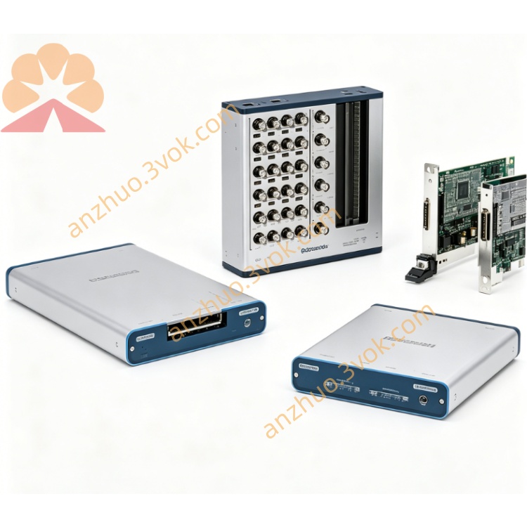
NI PXI-6704 16-Channel Analog Output DAQ Module
Description
II. Model Interpretation
PXI: Standard 3U single slot, compatible with PXI/PXIe mixed slots, supports PXI backplane power supply and trigger bus NI.
6704: 67xx analog output series, 4 represents 32 channels (16 voltages + 16 currents) for static output configuration, different from 6703 (16-channel voltages).
Positioning: High-density static DC output card, suitable for multi-channel, long-term stable control and excitation scenarios.
III. Technical Parameters (25℃)
1. Analog Output (AO)
Channel Configuration: 16 voltage + 16 current channels, a total of 32 channels, can output independently.
Resolution: 16 bits NI.
Voltage Range: -10.1 V ~ +10.1 V (each channel independently set) NI.
Current Range: 0.1 mA ~ 20.2 mA.
Output Drive: Voltage maximum ±10 mA; Current maximum 20.2 mA.
Accuracy: Voltage ±2 mV (typical); Current ±0.05 mA (typical).
Stability: Long-term drift <5 ppm/℃.
Update Mode: Static (no continuous refreshing, values remain stable) NI.
2. Digital I/O
Channels: 8 5V TTL/CMOS, input/output configurable NI.
Level: High ≥ 2.4 V, Low ≤ 0.4 V, maximum charging / discharging current 8 mA.
3. Physical and Environmental
Connector: 68-pin SCSI, compatible with shielded cables.
Power Supply: PXI backplane + 5 V/3 A, no external power required.
Operating Temperature: 0 ℃ ~ 70 ℃.
Storage Temperature: -20 ℃ ~ 85 ℃.
Power Consumption: Approximately 12 W.
IV. Interface and Communication Configuration
1. Hardware Interface
Front Panel: 68-pin SCSI-II, includes 32 AO, 8 DIO, power and ground, compatible with shielded cables to reduce noise.
Back Panel: Connect to PXI bus, supports PXI_TRIG trigger synchronization, backplane clock linkage.
2. Software and Drivers
Driver: NI-DAQmx, supports channel configuration, voltage/current output, digital I/O control, power-on status setting.
Development Environment: LabVIEW, C/C++, Python, TestStand, supports multi-module synchronous programming NI.
Function: Channel independent calibration, output range switching, fault diagnosis and status monitoring.
V. Core Functions
32-channel high-density static output
16 voltage + 16 current channels independently configured, 16-bit accuracy, suitable for multi-channel sensor excitation, actuator control, long-term stable without drift.
Each channel independent range and power-on status
Voltage/current channels can be individually set the range, supports custom power-on default values, avoiding abnormal output signals during system startup.
Integrated 8-channel TTL digital I/O
Balances analog output and switch quantity control, can directly drive relays, LEDs, or receive external switch signals, simplifying system architecture NI.
Static output, low resource consumption
No continuous refreshing (static retention), CPU usage extremely low, suitable for long-term running industrial monitoring and closed-loop control systems.
Multi-module synchronous and interlock protection
Supports PXI trigger bus synchronization, output timing deviation <1 μs when multiple cards output; software can configure output interlock, automatically safely shut down in case of faults.
VI. Application Scenarios
Industrial process control DC control for actuators such as valves, motors, and heaters, generation of 4-20 mA current loop signals, long-term stable output.
Sensor excitation and calibration
Provide precise ±10 V excitation source for pressure, temperature, and strain bridge circuits, calibrate sensor sensitivity and zero point.
Automated Test Equipment (ATE)
Static functional testing of circuit boards and modules, simulation of sensor output signals, verify the acquisition accuracy of DUT by NI.
Battery and power supply testing
Simulate battery voltage/current output, test power supply charging and discharging characteristics; verify the load characteristics of power supply module.
Laboratory precision DC signal source
Long-term stable power supply for scientific research equipment, bias voltage setting, low noise, high precision output.
VII. Installation and Maintenance Instructions
1. Installation and Power On
Disconnect power, insert into any slot of the PXI chassis, tighten screws and reliably ground; check the 68-pin cable for no short circuit before powering on to avoid damaging the output channel. Keep the chassis ventilated during operation, environmental temperature ≤ 70℃, to avoid temperature accumulation affecting accuracy.
2. Wiring and Operation
Cables: Use shielded 68-pin SCSI cables, separate analog and digital signals for wiring to reduce crosstalk; load resistance of current channel ≤ 500 Ω.
Configuration: Set channel type (voltage/current), range, power-on value in software; perform no-load debugging before connecting load, confirm normal accuracy before connecting load.
Synchronization: When synchronizing multiple cards, use PXI_TRIG trigger signal to ensure consistent output timing.
3. Daily Maintenance
Regularly clean 68-pin connectors, check the integrity of the cable shielding layer, add dust caps for long-term inactivity to prevent oxidation and dust from affecting contact reliability.
Calibration: Suggested once a year, use NI-DAQmx calibration tool, calibrate voltage/current accuracy, compensate for temperature drift.
Driver Update: Regularly update NI-DAQmx driver to fix compatibility issues and optimize output stability.
Get a Quote