
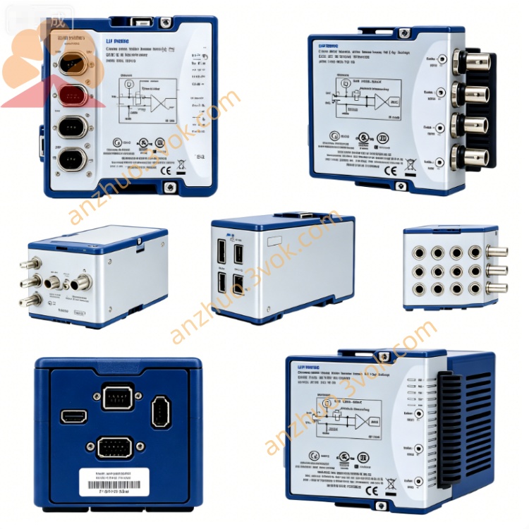
NI PXI-6624 Isolated 8-Ch Counter/Timer PXI Module
Description
II. Model Interpretation
PXI: Standard 3U single-slot module, compatible with PXI and PXIe mixed slots, supports PXI backplane trigger and synchronous bus.
6624: Belongs to the 662x industrial isolation counting DIO series, representing 8-channel counter, 48V industrial level, with isolated DIO configuration.
Overall positioning: Different from the conventional 5V TTL counting card, it focuses on industrial isolation, high-voltage level, and strong protection, suitable for on-site automation scenarios.
III. Technical Specifications (at 25℃ ambient temperature)
1. Counter / Timer
Channel quantity: 8 independent 32-bit add/subtract counters, maximum count value \(2^{32}-1\)
Reference clock: Optional 100 kHz, 20 MHz, clock accuracy 50 ppm
Maximum input counting frequency: 20 MHz
Signal measurement upper limit frequency: 400 kHz
Input level: Compatible with 5~48 V DC industrial signals; logic low ≤ 1.5 V, logic high ≥ 3.5 V
Core functions: Event counting, period/frequency measurement, pulse width/duty cycle detection, quadruplex frequency resolution of quadrature encoders, single pulse/continuous pulse, PWM output
PWM maximum output frequency: 1 MHz
2. Digital I/O
Digital Input: 26 isolated DI channels, supporting wide voltage input range of 5 to 48 V, with built-in overvoltage and reverse connection protection
Digital Output: 8 isolated DO channels, each channel rated at 100 mA, supporting current injection / pull, with built-in short-circuit protection
Isolation Specifications: 60 V DC isolation between channels, 2500 Vrms insulation withstand voltage between I/O side and module bus
3. Physical and Environmental Parameters
Form factor: 3U single-slot structure
Typical power consumption: 6 W
Connector: 100-pin shielded SCSI interface
Operating temperature: 0 ℃ ~ 55 ℃, extended temperature range up to -40 ℃ ~ 85 ℃
Electromagnetic protection: ESD ±15 kV, surge ±2 kV, electrostatic transient pulse ±2 kV
IV. Interface and Communication Configuration
1. Hardware Interface
Peripheral interface: 100-pin SCSI interface, integrated counter signal, 26 channels of DI, 8 channels of DO, isolated power supply and common ground.
Synchronization interface: Supports PXI backplane trigger bus, STAR trigger, external PFI signal, multi-module synchronization error less than 100 ns.
Bus characteristics: PXI standard bus, equipped with 3 independent DMA channels, capable of achieving high-speed continuous data transmission and reception, reducing system resource occupation.
2. Software and Drivers
Supporting driver: NI-DAQmx (version 7.5 and above), equipped with a dedicated debugging panel for counters.
Development support: Compatible with mainstream development environments such as LabVIEW, Python, C/C++, and TestStand.
V. Core Functions
Isolated industrial counting: 8 independent 32-bit counters, directly connected to 24 V/48 V industrial encoders and pulse sensors. Channel isolation can eliminate ground potential difference interference, suitable for long-term stable operation in strong electromagnetic environments.
Integrated isolated DIO: 26 inputs for collecting on-site switches, limit switches, and sensor states; 8 outputs can directly drive small relays and solenoid valves. All channels integrate multiple electrical protections, no need for additional external protection circuits.
Multifunctional pulse control: supports orthogonal encoder decoding, high-frequency pulse measurement, and PWM speed output, meeting the requirements of position and speed closed-loop control for motion systems.
High-speed continuous transmission: 3 DMA channels support uninterrupted event recording and pulse stream output, suitable for high-speed production lines and multi-axis linkage control scenarios.
Industrial-grade reliable protection: comprehensive anti-interference design against static electricity, surges, and pulse clusters, wide temperature operating range, suitable for harsh working conditions such as workshops, vehicles, and outdoors.
VI. Applicable Scenarios
Factory Automation: Production line workstation counting, equipment speed monitoring, limit switch signal collection, on-site relay and valve control.
Motion Control System: Servo, stepper motor encoder position and speed feedback, origin/limit detection, PWM motor speed control, pulse direction control.
Automotive Electronic Testing: Vehicle equipment speed pulse collection, body switch status monitoring, vehicle motor and light PWM control.
Energy and Heavy Machinery Equipment: Wind power, photovoltaic equipment pulse measurement, large machinery encoder position monitoring, high-voltage cabinet switch status collection.
Industrial Automation Testing: Household appliances, industrial control board card function testing, relay lifespan testing, isolated pulse signal verification.
VII. Installation and Maintenance Instructions
1. Installation and Power On
Insert the module into the PXI chassis slot while the power is off, lock the fixing screws to ensure reliable grounding of the chassis. After powering on, the hardware self-check will be automatically completed without preheating. During operation, keep the air duct of the chassis unobstructed to avoid overheating.
2. Wiring and Operation
It is recommended to use the dedicated adapter cable and isolation junction box to reduce frequent plugging and unplugging of interfaces. Connect strictly according to the 5-48 V voltage specification. Do not use beyond the rated voltage. For long-distance wiring, choose shielded cables. Keep the cables away from strong interference devices such as motors and frequency converters. Use shielded cables for high-frequency pulse signals, and enable software filtering for low-frequency contact signals to eliminate jitter.
3. Daily Maintenance
Regularly clean the interface dust, check the tightness of the connection terminals to avoid poor contact. Install interface dust covers when the module is idle for a long time. The module is a pure digital circuit and does not require regular calibration; annual inspections can be conducted to test the insulation isolation performance and cable integrity based on the usage environment. Update the supporting drivers and firmware in a timely manner to ensure functional stability.
Get a Quote