
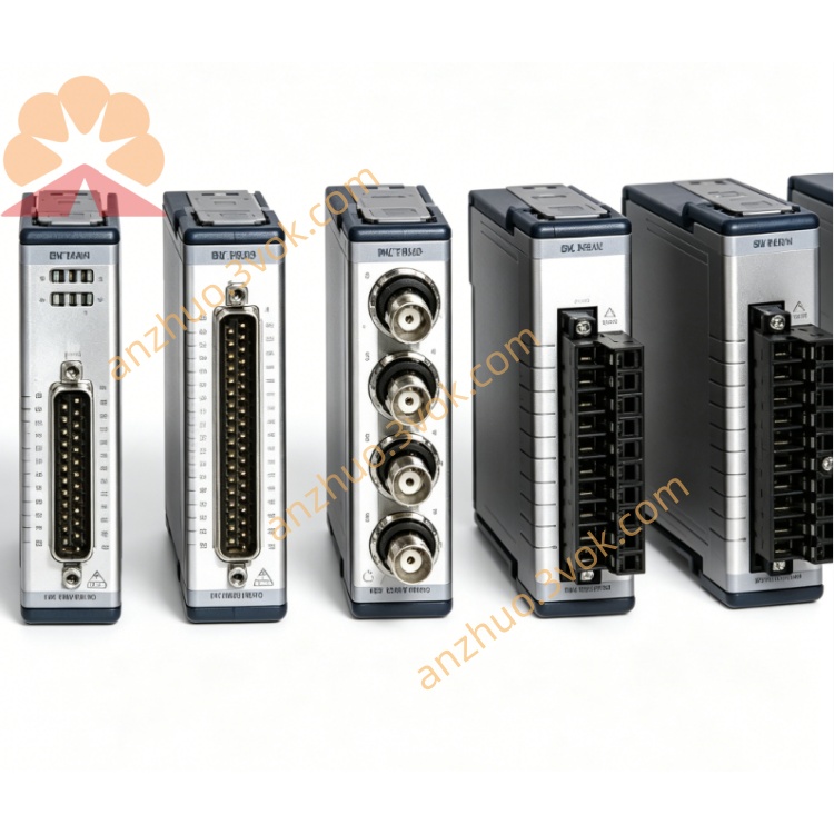
NI PXI-6533 32CH High-Speed Handshaking Digital I/O Module
Description
II. Model Interpretation
PXI: Compliant with the PXI bus standard, 3U single-slot specification, compatible with both PXI and PXIe mixed slots.
6533: Belongs to the NI 653x high-speed DIO series, "653" represents high-speed bidirectional digital I/O, and the "3" at the end indicates the 5V TTL level version (corresponding to 6534 as the 3.3V version).
Core Identifier: 32 bidirectional, non-isolated, 5V TTL/CMOS, high-speed DMA handshake.
III. Technical Parameters (25℃)
General Parameters
Channel Configuration: 32 independent configurable bidirectional I/O, divided into 4×8-bit ports (Port0~Port3) by NI.
Voltage Level: 5V TTL/CMOS, absolute maximum voltage -0.3 V to +5 V.
Drive Capacity: 24 mA per channel for driving TTL devices, relays, LEDs, etc. directly.
Port Grouping: Supports 8/16/32-bit combinations, suitable for different bit-width parallel interfaces.
Rate and Transmission
Static I/O: Single-point read/write, no rate limit.
Mode I/O (sequence generation/collecting): Up to 2 MHz (13.3 MB/s).
Handshake I/O (DMA high-speed transmission): Up to 77.8 MB/s, supporting 6 industrial handshake protocols (such as Strobe, Acknowledge).
Trigger Synchronization: PXI trigger bus, star trigger, 10 MHz reference clock, supports multi-module synchronization.
Physical and Environmental
Size: 3U single-slot (160×100 mm).
Power Consumption: +5 V@2 A (maximum 4.65~5.25 W).
Connector: 68-pin SCSI-II female connector.
Operating Temperature: 0~55℃ (commercial grade).
Certification: UL, CE, compliant with PXI specifications.
IV. Interface and Communication Configuration
Hardware Interface
Front Panel: 68-pin SCSI-II female connector, keyed to prevent incorrect insertion.
Adapter Cable: SH68-68 (68-pin to 68-pin), SH68-100 (adapter for 100-pin terminals).
Terminal Box: CB-68 (68-pin universal terminal box), SCB-68 (with shielding terminal box).
Bus and Driver
Bus: PXI bus (PCI protocol), supports DMA bus master mode, reduces CPU usage.
Driver Software: NI-DAQmx, compatible with LabVIEW, Python, C#, TestStand, etc. development environments.
Synchronization Mode: PXI trigger bus / RTSI, multi-modules can achieve nanosecond-level timing synchronization.
V. Core Functions
32 independent bidirectional I/O: Each channel can be software-configured as input or output, 5V TTL/CMOS compatible, 24 mA drive, suitable for various digital devices and actuators.
Three-level working modes
Static I/O: Single-point read/write, used for status monitoring, switch control, LED indication.
Mode I/O: High-speed sequence generation/collecting (2 MHz), suitable for I2C/SPI/UART protocol simulation, timing verification.
Handshake I/O: DMA + 6 handshake protocols, 77.8 MB/s, suitable for high-speed peripherals, memory, parallel interface testing.
Flexible Synchronization and Security Mechanism: Supports PXI trigger / star trigger, multi-module synchronous acquisition; programmable power-on state + watchdog, preventing abnormal output from damaging the equipment. Core of high-density ATE test: Single card replaces multiple discrete I/O chips, achieving 32-line parallel testing, fixture status acquisition, relay matrix control, and boundary scan testing.
Six. Application Scenarios
PCB Function Testing (FCT): 32-channel parallel I/O simulates I2C/SPI/UART protocols, collects contact/sensor states, drives relays, electromagnetic valves, etc. as actuators.
Semiconductor/Electronic Device Testing: Chip pin level testing, timing verification, boundary scan, high-speed digital signal acquisition/generation, logic device functional testing.
Industrial Automation High-Speed Control: PLC high-speed expansion module, rapid status acquisition + actuator control in production line, servo/stepper motor pulse output, high-speed sorting system.
Instrument and Communication Testing: High-speed data recording, parallel interface simulation, custom bus protocol development, multi-device synchronous testing, radar/communication module digital interface testing.
Automotive Electronics Testing: On-board ECU digital I/O testing, contact monitoring of body control module (BCM), testing of automotive lighting/windshield control systems.
Seven. Installation and Maintenance Instructions
Installation and Power On
Installation: Insert the PXI chassis 3U slot in the power-off state, ensure the chassis is reliably grounded to avoid static damage.
Power On: Connect the chassis power supply, NI-DAQmx automatically self-checks, no preheating required, after the self-check passes, it can be used.
Environment: Working temperature 0~55℃, keep the chassis ventilation ducts unobstructed, avoid over-temperature reduction; away from strong electromagnetic interference sources (such as motors, frequency converters).
Connection and Operation
Connection: Avoid frequent plugging and unplugging of 68-pin interface, recommend using the CB-68 wiring box for intermediate transfer; input signal voltage **≤5 V**,严禁 overvoltage; use shielded twisted pair for long-distance transmission, single-ended grounding of the shield layer.
Configuration: Configure channel direction (input/output), power-on state, filtering time through NI-DAQmx; in high-speed mode, preferentially use DMA handshake transmission to reduce CPU usage.
Protection: Avoid short-circuit of output channels, when driving inductive loads (such as relays, motors), need to parallel a shunt diode.
Daily Maintenance
Interface: Regularly clean the 68-pin interface to avoid dust and oxidation causing poor contact; install a dust cover when the device is idle for a long time.
Software: Regularly update the NI-DAQmx driver to fix bugs and improve compatibility.
Calibration: No need for regular calibration, photoelectric isolation and digital circuits are stable for a long time; check the connection terminal tightness once a year to avoid loosening.
Get a Quote