
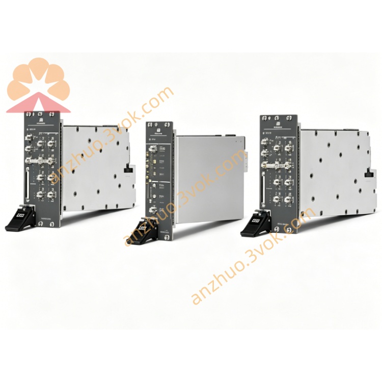
NI PXI-6527 48CH Isolated Digital I/O Module
Description
II. Model Interpretation
PXI: 3U single slot, standard PXI bus (compatible with PXIe hybrid slots)
6527: 652x Isolated DIO series, full-channel opto-isolation + solid-state relay output model
Architecture: 24 independent opto-isolated DI; 24 independent solid-state relay DO, completely isolated between channels
Part Number: 777802-01
Position: High-reliability non-contact switch + preferred choice for strong interference environment monitoring
III. Technical Parameters (25℃)
1. Digital Input (DI)
Channels: 24 independent opto-isolated DI
Voltage range: 3–28 VDC (compatible with 24 V industrial standard)
Logic threshold: High ≥ +11 V, Low ≤ +4 V
Isolation: Channel-to-channel 2500 Vrms (1 minute), Channel-to-ground 2500 Vrms
Input filtering: Hardware fixed + software programmable debounce
Response delay: Typical 150 μs
2. Solid-state Relay Output (DO)
Channels: 24 independent solid-state relay DO (no contacts)
Switch voltage: 0–30 VDC
Switch current: 120 mA/channel continuous
Isolation: Channel-to-channel 2500 Vrms, Channel-to-ground 2500 Vrms
Output capacitance: 55 pF @1 V
Power-on state: Programmable (all off / all on)
Output readback: Supports software reading of output status (diagnostic verification)
3. Physical and Environment
Size: 3U single slot (22×124×126 mm)
Operating temperature: 0–55℃
Power consumption: Approximately 2.0 W
Certifications: UL, CE, Measurement Class II
IV. Interface and Communication Configuration
Front panel interface: 68-pin SCSI female connector (dumb design)
Adapter cable: SH68-68, R6805050 (68-pin adapter)
Terminal box: CB-68, SCB-68A (with isolation terminals)
Bus: PXI (PCI, trigger, 10 MHz reference clock)
Driver: NI-DAQmx, supports LabVIEW, Python, C#, TestStand
Synchronization: PXI trigger bus, multi-module synchronous acquisition and control
V. Core Functions
24DI High Isolation + 24DO Solid-state Non-contact: Single card monitoring of 24 channels of 24 V sensors + driving of 24 small-power DC loads, 2500 Vrms channel-to-channel isolation completely cuts off ground loop current, non-contact solid-state relay lifespan ≥ 1 billion times, far exceeding mechanical relays.
Industrial-grade strong anti-interference: Full-channel opto-isolation + high voltage rating 2500 Vrms, resistant to motor, frequency converter, high-voltage surge interference, suitable for harsh industrial environments.
Output readback diagnosis: Software can read the actual state of the output relay, closed-loop verification of control logic, simplifies system debugging and fault troubleshooting.
Wide voltage input compatibility: 3–28 VDC input range, compatible with global 24 V industrial sensors (NPN/PNP universal).
High-density single slot: 48 channels 3U single slot, saves chassis slots, suitable for large-scale I/O isolation systems.
VI. Application Scenarios
Industrial Automation "High-reliability Monitoring + Non-contact Control": PLC expansion isolation DIO, 24 V sensor acquisition + indicator lights / small relays driving, production line status feedback + non-contact actuator control.
Power and Energy Systems: Switch cabinet status monitoring + small power coil driving, relay protection contact acquisition, high-voltage isolation monitoring circuit. Automotive electronic testing: Binary quantity collection for BCM + Low-power load driving for vehicle lights / door locks, 12/24 V system isolation monitoring.
ATE and test system: Test fixture status collection + Relay matrix control, Power supply circuit isolation on/off, Safety interlock signal closed-loop.
Railway / Ship Control: Isolated monitoring of on-board / shipboard binary quantities + Control of low-power actuators, High-reliability I/O in strong interference environment.
VII. Installation and Maintenance Instructions
Installation and Power On
Disconnect the card and ensure the chassis is reliably grounded; Power on and the NI-DAQmx self-checks, no preheating required.
Operating Temperature: 0–55℃. Keep the air duct unobstructed and avoid overloading due to high temperature.
Wiring and Operation
Avoid frequent plugging and unplugging of 68-pin interface; It is recommended to use the CB-68 isolation wiring box for intermediate transfer.
Input Voltage: **≤28 VDC**, Output Current: **≤120 mA/channel**, Do not short circuit; Use shielded twisted pair for long-distance, keep away from strong electricity / motors.
Filtering Time: Set according to contact characteristics (10–50 ms), Watchdog Timeout Time: Set according to safety requirements (100–500 ms).
Daily Maintenance
Keep the interface clean, prevent dust accumulation when idle for a long time; No calibration required, regularly check the tightness of wiring terminals.
Solid-state relays have no mechanical wear, long service life, and do not need frequent replacement; Isolation layer is subject to regular insulation tests (2500 Vrms/1 minute).
Get a Quote