
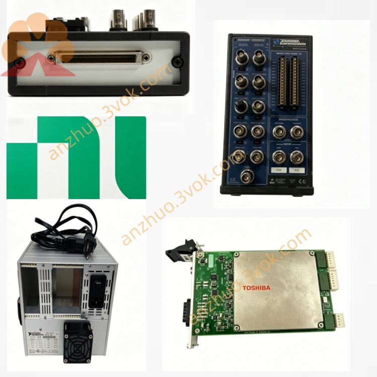
NI PXI-6511 64CH Bank-Isolated Digital Input Module
Description
II. Model Interpretation
PXI: 3U single slot, standard PXI bus (compatible with PXIe mixed slots)
6511: 651x series (industrial isolated DIO), 64-channel isolated input basic version
Core Architecture: 8 groups (Bank) × 8 channels, electrical isolation between groups
Part Number: 778967-01
Status: In production; no direct replacement, check PXI-6512/6513 for series upgrade
III. Technical Parameters (25℃)
1. Digital Input (DI)
Channels: 64 isolated inputs, divided into 8 groups (Bank 0–7), 8 channels per group
Voltage range: -30 VDC to +30 VDC (compatible with 24 V industrial logic)
Input type: Current injection / pull (Sink/Source) compatible
Isolation: Group-to-group isolation (250 Vrms, 1 minute), channel-to-channel common ground
Threshold: Logic high ≥ +10 V, logic low ≤ +5 V (24 V system)
Input impedance: 10 kΩ (typical)
Filtering: Software programmable digital filtering (debouncing / de-scrambling)
Change detection: Level change triggers interrupt
Watchdog: Software failure automatically switches to safe state
2. Physical and Environmental
Size: 3U single slot (22×124×126 mm)
Operating temperature: 0–55℃ (industrial extended -20–70℃ optional)
Power consumption: 300 mA @ +5 V (approximately 1.5 W)
Calibration: No regular calibration required (pure digital module)
IV. Interface and Communication Configuration
Front panel interface: 100-pin SCSI female connector (dumb key position)
Adapter cable: SH100-100, R1005050 (100-pin to 2×50-pin)
Terminal box: CB-100, SCB-100A (with isolation terminals)
Bus: PXI (PCI, trigger, 10 MHz reference clock)
Driver: NI-DAQmx 9.0+, supports LabVIEW, Python, C#, TestStand
Synchronization: PXI trigger bus, multi-module synchronous acquisition
V. Core Functions
64-channel isolated input + ±30 V wide voltage range: compatible with 24 V industrial sensors, relays, switches, group-to-group isolation to resist ground current and high-voltage interference.
Industrial-grade reliability: watchdog + programmable filtering + change detection, software crash automatic protection, debouncing adapted to mechanical contacts.
Current injection / pull compatible: supports NPN (Sink)/PNP (Source) sensors simultaneously, no additional circuit required.
High-density single slot: 64-channel 3U single slot, saves chassis slots, suitable for large-scale I/O monitoring.
Safety isolation design: 250 Vrms group-to-group isolation to prevent high-voltage from entering the PXI system, protecting equipment and personnel safety.
VI. Application Scenarios
Industrial automation status monitoring: PLC expansion DI, 24 V sensor array, relay/contactor status feedback.
Power and energy systems: high-voltage switch cabinet status, circuit breaker / disconnect switch position, relay protection contact monitoring.
Automotive electronic testing: body control module (BCM) switch quantity, door / lamp / wiper status collection.
ATE and test system: large-scale relay matrix monitoring, PCB test fixture status, safety interlock signal.
Railway / ship control: on-board/off-board switch quantity, door control / lights / alarm signal, monitoring in high-interference environments.
VII. Installation and Maintenance Instructions
Installation and Power On
Disconnect power, plug the card, and ensure reliable grounding of the chassis; After powering on, NI-DAQmx performs self-check without preheating.
Operating temperature: 0–55℃. Keep the ventilation duct unobstructed and avoid over-temperature reduction.
Connections and Operations
Avoid frequent plugging and unplugging of the 100-pin interface. It is recommended to use the CB-100 isolation connector box for intermediate connection.
Input voltage: **≤ ±30 V**. Do not exceed the voltage; use shielded twisted-pair cables for long-distance connections and keep away from strong electricity / motors.
Set the filtering time according to the contact characteristics (10–50 ms) to avoid jitter triggering errors.
Daily Maintenance
Keep the interface clean and prevent dust accumulation during long-term inactivity; no calibration required, and regularly check the connection terminal tightness.
Perform regular insulation tests on the isolation layer (250 Vrms/1 minute) to ensure isolation performance.
Get a Quote