
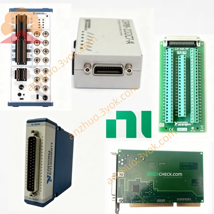
NI PXI‑6508 96‑Channel 5V TTL/CMOS Digital I/O Module
Description
II. Model Interpretation
PXI: 3U single slot, standard PXI bus (compatible with PXIe mixed slots)
6508: 65xx series (static DIO), 96-channel high-density version
Core Architecture: 4 pieces of 24-bit PPI (programmable peripheral interface), each piece divided into 3 8-bit ports (A/B/C)
Part Number: 777598-01
Status:discontinued;
III. Technical Parameters (25℃)
1. Digital I/O (DIO)
Channels: 96 bidirectional (5 V TTL/CMOS), divided into 12 8-bit ports
Drive Capacity: 2.5 mA (sinking / sourcing current) per channel
Level: High ≥ 2.0 V, Low ≤ 0.8 V
Input Resistance: 10 kΩ (typical)
Pull-up / Pull-down: Optional (via jumper W1), default pull-up
Power-On State: Configurable (high / low / open drain)
Transmission Rate: Up to 50 KB/s (software timing)
2. Port Configuration
4×PPI (82C55), each PPI contains 3×8-bit ports (A: input/output; B: input/output; C: control/status/handshake)
Supports 2-wire handshake, interrupts, programmable I/O transmission
3. Physical and Environmental
Size: 3U single slot (22×124×126 mm)
Operating Temperature: 0–55℃
Power Consumption: 400 mA @ +5 V (approx. 2 W)
Calibration: No regular calibration (pure digital module)
IV. Interface and Communication Configuration
Front Panel Interface: 100-pin D-Type female connector (0.050 pitch)
Adapter Cable: R1005050 (100-pin to 2×50-pin), SH100-100
Terminal Box: CB-100, SCB-100A
Bus: PXI (PCI slave mode, no DMA)
Driver: NI-DAQ (traditional), supports LabVIEW, C/C++, Visual Basic
Synchronization: No hardware trigger, dependent on software handshake
V. Core Functions
Ultra-high Density Digital I/O: 96-channel single card, covers a large number of switches / sensors / actuators, saves slots and costs.
Flexible Port Partitioning: 12 independent 8-bit ports, can be grouped configured for input/output, suitable for different peripherals.
Reliable Static Control: 5 V TTL compatible, 2.5 mA drive, suitable for relays, LEDs, switch quantity sensors.
Handshake and Interrupt Support: 2-wire handshake simplifies timing synchronization with peripherals, interrupts improve response efficiency.
Power-On State Controllability: Avoids incorrect actions during system startup, enhances safety.
VI. Application Scenarios
Industrial ATE Switch Matrix: Large-scale relay/contactor control, PCB test channel switching.
Sensor Array Monitoring: 96-channel switch quantity / proximity switch / photoelectric sensor synchronous acquisition.
Equipment Status Monitoring: PLC expansion I/O, cabinet indicator lights, valve/motor start/stop control.
Laboratory Automation: Multi-station fixture control, sample positioning, safety interlock signals.
General Digital Measurement and Control: Mixed systems requiring high density, low cost, static digital I/O.
VII. Installation and Maintenance Instructions
Installation and Power On
Disconnect power, ground the chassis; power on after NI-DAQ self-check, no preheating required.
Operating Temperature: 0–55℃, keep the air duct unobstructed, avoid high temperature.
Connection and Operation
Avoid frequent plugging and unplugging of 100-pin interface, recommend using CB-100 terminal box for intermediate transfer.
Output drive **≤ 2.5 mA / channel**, preventing overcurrent damage; input voltage **≤ 5.5 V**.
Long-distance signals use shielded twisted pair cables to reduce interference; keep away from strong electricity / motors.
Daily maintenance
Keep the interface clean, prevent dust accumulation during long-term inactivity; no calibration required, regularly check the tightness of the connection terminals.
Get a Quote