
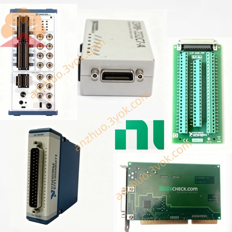
NI PXI‑6031E E‑Series Multifunction DAQ Module
Description
II. Model Interpretation
PXI represents that the equipment follows the PXI industrial bus standard and adopts a 3U external structure, occupying a single cabinet slot, and is compatible with both PXI and PXIe cabinets.
6031E belongs to the NI E series of data acquisition products, being a classic high-precision acquisition module of the same series, positioned as a 16-bit resolution, high sampling rate multi-functional I/O module.
The standard complete component number is 777556-01.
III. Technical Parameters
The following parameters are typical values under a constant temperature of 25 degrees Celsius.
1. Analog Input
Channel configuration: 16 single-ended inputs or 8 differential inputs, which can be switched by software.
Sampling resolution: 16 bits.
Maximum total sampling rate: 166 kilosamples per second.
Programmable voltage range: 0.1 volt to 10 volts positive and negative, with multiple selectable ranges.
Input impedance: 1 megohm.
Input coupling mode: DC coupling.
Input protection: Can withstand positive and negative 25 volts overvoltage when powered on, and positive and negative 15 volts overvoltage when powered off.
Linear accuracy: Positive and negative 0.5 least significant bit, differential non-linearity does not exceed 1 least significant bit.
2. Analog Output
Channel quantity: 2 channels
Output resolution: 16 bits
Standard output range: Positive and negative 10 volts
Output drive current: Positive and negative 5 milliamps
Single-channel maximum refresh rate: 100 kilosamples per second
Output impedance: No more than 0.1 ohm
3. Digital Input Output
Channel quantity: 8 bidirectional digital channels
Electrical standard: Compatible with TTL level
Highest working rate: 1 megahertz
4. Counter Timer
Channel quantity: 2 24-bit counters
Supported functions: event counting, frequency measurement, period measurement, pulse signal output
Internal reference clock: 100 megahertz
5. Physical and Environmental Parameters
Equipment specification: 3U structure, single slot
Operating temperature range: 0 degrees Celsius to 55 degrees Celsius
Overall power supply: Powered by the backplane of the PXI cabinet
Operating humidity: 10% to 90%, no condensation in the environment
IV. Interface and Communication Configuration
External Interfaces
The equipment is equipped with a 68-pin SCSI standard interface, used for external signal cables and terminal blocks. All analog signals, digital signals, and counter signals are led out through this interface. The equipment has no external status indicator light. The operating status and fault information are read through the accompanying software.
Bus and Software Configuration
The equipment backplane is equipped with a standard PXI bus, including PCI bus, PXI trigger bus, and 10 megahertz reference clock bus.
The accompanying driver program is NI-DAQmx, which can be used in mainstream development environments such as LabVIEW, TestStand, Python, and C#.
Supports PXI trigger bus and RTSI bus, enabling clock synchronization and trigger synchronization of multiple modules.
V. Core Functions
1. High-resolution signal acquisition, with 16-bit sampling accuracy capable of accurately capturing weak analog signals, and differential input mode effectively suppresses common-mode interference in industrial sites.
2. Medium-high sampling capability, with sufficient overall sampling rate to meet the requirements of synchronous and quasi-synchronous acquisition of multiple signals.
3. Integrated multi-function design, integrating analog input, analog output, digital ports, and counters. One module can complete measurement and basic control.
4. Rich range configuration, with multiple voltage range selectable options to adapt to different types of sensors and measured equipment, with strong universality.
5. Good expansion and synchronization capabilities, supporting multi-module cascading synchronization operation, enabling the construction of large-scale multi-channel measurement and control systems.
6. Built-in hardware overvoltage protection, enhancing equipment operation safety, suitable for complex industrial usage environments.
VI. Application Scenarios 1. Industrial process measurement and control, used for high-precision monitoring and closed-loop control of analog quantities such as temperature, pressure, flow, and liquid level in the production site.
2. Precision sensor testing, suitable for collecting low-level signals such as thermocouples, thermoresistors, strain sensors, and photoelectric sensors.
3. Laboratory research and teaching, used for recording, data analysis, and equipment verification of signals in physics, chemistry, and biology-related experiments.
4. Function testing of electronic products, conducting static and dynamic parameter detection of circuit boards and electronic components.
5. Motion and timing control, using the counter function to achieve speed measurement, position detection, and pulse instruction output functions.
7. Installation and Maintenance Instructions
Installation and Power On
The equipment must be inserted into a single slot of the chassis in an off-power state. The chassis should be reliably grounded to prevent static damage to the circuit.
After installation is completed, connect the power supply and use the accompanying driver software to perform equipment self-check to confirm the normal hardware.
During equipment operation, ensure that the air duct of the chassis is unobstructed, and the environmental temperature is maintained between 0 degrees Celsius and 55 degrees Celsius. Do not block the cooling fan.
Cable Connection and Operation
Shielded cables should be used for analog signals. In noisy environments, differential connection methods are recommended.
Connect signals strictly according to the range specifications. The input voltage must not exceed the rated range of the equipment.
68-pin interface should not be frequently plugged and unplugged. It is recommended to use a dedicated wiring box to connect the lines and reduce interface wear.
When synchronously collecting multiple modules, use the 10 MHz reference clock and trigger signal of the chassis.
Daily Maintenance and Calibration
It is recommended to conduct professional traceability calibration once a year to correct the gain and offset errors caused by long-term use of the equipment. Daily use can compensate for parameter drift caused by temperature changes by using the built-in self-calibration function of the equipment.
Regularly check the external interfaces and cables, keep the interfaces clean and dry. When the equipment is idle for a long time, take dust-proof measures.
The operating environment should be free of condensation and away from strong electromagnetic interference sources and severe vibration sources.
Do not plug or unplug signal cables while the equipment is powered on. Take electrostatic protection measures during the operation process.
Get a Quote