
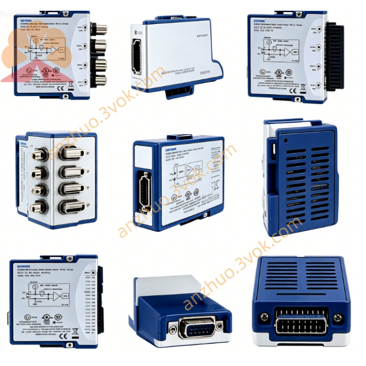
NI PXI‑5406 40MHz 16‑Bit PXI Waveform Generator
Description
II. Model Interpretation
PXI: 3U PXI standard bus, single slot, compatible with PXI/PXIe chassis.
5406: NI 5400 series waveform generator, meaning:
54xx: Arbitrary waveform / function generator series
x4x: Analog output, bandwidth 20–40 MHz
xx06: 1-channel, 16-bit, 40 MHz high-end version (compared to 5402: 14-bit, 20 MHz)
Part number: 779657-01 (standard for PXI-5406).
III. Technical Parameters (25℃, 50 Ω termination, typical values)
1. Basic Performance
Channel number: 1 analog output
Resolution: 16-bit DAC (2 bits higher than 5402)
Bandwidth (–3 dB): 40 MHz (sine / square wave)
Output amplitude: 10 Vpp (±5 V) @ 50 Ω; software adjustable ±1 V to ±5 V
Output impedance: 50 Ω / 75 Ω software selectable (5402 fixed 50 Ω)
Sampling rate: basic 100 MS/s; after interpolation ×4, equivalent 400 MS/s
Frequency resolution: 0.355 μHz (DDS, phase continuous)
2. Standard waveform frequency upper limit
Sine / square wave: 40 MHz
Triangle / sawtooth: 5 MHz
Noise / DC: full bandwidth
3. Storage and Filtering
Arbitrary waveform memory: 32 kB / channel (user-defined)
Digital filtering: FIR interpolation (×2/×4, software selectable)
Analog filtering: 7th-order elliptic low-pass (software switch)
4. Synchronization and Timing
Synchronization technology: NI-TClk (multi-card ps-level synchronization)
Trigger / clock: PXI trigger bus, REF IN/OUT (10 MHz), PFI
Harmonic suppression: <–65 dBc @10 MHz (typical, better than 5402)
5. Environment and Power Consumption
Operating temperature: 0–55℃
Storage temperature: –40–70℃
Power consumption: approximately 13 W
Size: 3U single slot (about 160×100 mm)
IV. Interface and Communication Configuration
Front panel (single-slot cover, 4×BNC)
CH0 (BNC): analog output, 50/75 Ω selectable, ±5 Vmax
REF IN (BNC): external reference clock input (10 MHz, PLL lock)
REF OUT (BNC): internal 10 MHz reference output
PFI0 (BNC): programmable trigger input / output
Bus and system interface
PXI backplane: 32-bit PCI, PXI trigger bus (TRIG0–TRIG6), RTSI
Synchronization clock: routable internal sampling clock / reference clock to:
front panel REF IN/OUT, PFI0
PXI trigger bus, RTSI bus (multi-card synchronization)
Software driver
Driver: NI-FGEN (standard)
Support environment: LabVIEW, TestStand, Python, C#, LabWindows/CVI
Configuration tool: NI MAX (device management / calibration), soft front panel SFP
V. Core Functions
16-bit high-resolution output: ±5 V range, 16-bit, low noise, low distortion, suitable for precise analog excitation.
40 MHz wideband signal generation: sine / square wave up to 40 MHz, covering mid-high frequency test requirements. DDS Precise Frequency Synthesis: 0.355 μHz resolution, continuous phase frequency hopping / sweeping, low jitter.
Multi-impedance Adaptation: 50 Ω/75 Ω software switching, suitable for RF / communication / video loads.
ps-level Multi-Instrument Synchronization: NI-TClk synchronizes with PXI oscilloscopes, digital cards, etc., to build a mixed-signal test station.
Rich Modulation and Sequences: AM/FM/PM, sweeping, burst, phase-coherent multi-sequence output.
Six. Application Scenarios
Mixed-signal Testing: High-precision amplifiers, filters, ADC/DAC above 16 bits, PMIC excitation verification.
Semiconductor Testing: Precise analog chips, RF front-end, high-speed interfaces (USB/PCIe) timing verification.
Automotive Electronics: High-precision sensor simulation, ADAS signal simulation, ECU precise excitation testing.
Research and Education: Precise physics experiments, biological electrical signal simulation, high-frequency signal processing teaching.
PXI System Integration: Synchronizes with PXI oscilloscopes, high-speed digital I/O, switch matrix to build an automated test platform.
Seven. Usage and Maintenance Instructions
1. Installation and Power On
Power off installation, fixed in a single slot; the chassis is reliably grounded to prevent static electricity.
Power on preheating for 15 minutes, no hardware errors detected by NI MAX self-check.
Keep ventilation during operation, temperature ≤ 55℃, do not block the chassis fan.
2. Wiring and Operation
High-frequency signals use 50 Ω high-precision coaxial cables, tighten the BNC connection to reduce reflections.
Output short-circuit is prohibited; load matching (50/75 Ω), avoid overcurrent damage.
Amplitude setting does not exceed ±5 V; for high-frequency (>1 MHz), use AC coupling preferentially.
Multi-card Synchronization: Enable NI-TClk, share 10 MHz reference clock to ensure phase consistency.
3. Calibration and Maintenance
Calibration Cycle: It is recommended to conduct NIST traceable calibration once every 2 years; use internal self-calibration to compensate for temperature drift on a daily basis.
Interface Maintenance: Clean the BNC interface regularly to keep it dry; add a dust cap for long-term inactivity.
Environmental Requirements: No condensation, humidity 10%–90% RH; keep away from strong electromagnetic interference and vibration.
Prohibited: Do not plug or unplug cables while powered on, do not subject to severe vibration, do not operate at excessive temperature.
Get a Quote