
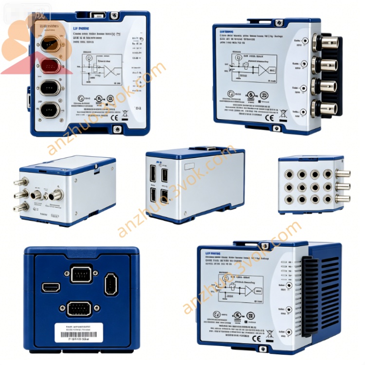
NI PXI‑4498 24‑Bit 16‑Channel Sound and Vibration DAQ Module
Description
Model Explanation
PXI: Standard 3U PXI bus, single slot, compatible with PXI/PXIe chassis.
4498: NI 449x series number, representing 16-channel analog input, 24-bit, 204.8 kS/s, IEPE, AC coupling, high-density acoustic vibration-specific.
Part Number: 779747‑01 (standard); 779747‑02 (with acoustic vibration measurement kit).
Technical Parameters (25℃, preheating 15 min)
Channels: 16 differential analog inputs, full-channel synchronous sampling.
ADC: 24-bit Σ‑Δ type.
Sampling Rate: Single channel up to 204.8 kS/s.
Dynamic Range: Typical 114 dB.
Input Voltage Range: ±316 mV, ±1 V, ±3.16 V, ±10 V.
Gain: 0 dB, +10 dB, +20 dB, +30 dB (software selectable).
Coupling: AC coupling, -3 dB cut-off 0.5 Hz (strong low-frequency performance).
IEPE Conditioning: Software controllable 4 mA constant current, compliant voltage 24 VNI.
Input Impedance: Voltage mode 100 kΩ; IEPE mode 10 kΩ.
Anti-aliasing Filter: Built-in programmable, automatically adjusted with sampling rate, no aliasing bandwidth 90 kHz.
THD+N: ≤‑100 dB; CMRR (1 kHz) >60 dB.
Trigger: Dual SMB external trigger, TTL level, rising/falling edge, minimum pulse width 10 ns.
Power Supply: PXI backplane power supply; maximum power consumption approximately 18 W.
Connectors: 2×InfiniBand 4x (each port 8 channels), can be converted to BNCNI.
Size/Weight: 3U single slot, approximately 320 g.
Environment: Operating 0~55℃; accuracy guaranteed 15~35℃; storage -20~70℃.
Calibration: Recommended 1 year, supported NIST traceability.
Interface and Communication Configuration
Front-end Interface
2×InfiniBand 4x: divided into two groups (AI0‑7, AI8‑15), a total of 16 analog inputs from NI.
2×SMB: trigger input/output, compatible with PFI/PXI trigger bus from NI.
Panel Indicator Lights
PWR (green): normal power supply.
RUN (green): constantly on = sampling in, flashing = waiting for trigger.
ERR (red): over-temperature, over-current or calibration error.
Bus and Synchronization
PXI bus, compatible with PXIe; supports PXI trigger, RTSI synchronization.
Multi-module synchronization skew <1 μs; single chassis up to 18 modules, synchronizing 288 channels.
Software Driver
NI‑DAQmx, supports LabVIEW, TestStand, Python, C#.
NI MAX: device identification, self-check, configuration, calibration.
Companion: Sound and vibration measurement kit, order analysis toolkit. Core function
16-channel synchronous acquisition: Full-channel synchronous delay < 1 μs, high-density multi-measurement point synchronous measurement.
Ultra-high dynamic range: 114 dB, simultaneously capturing weak and strong amplitude signals.
Integrated IEPE calibration: 4 mA constant current, directly driving IEPE accelerometers/microphones NI.
24-bit high precision + low noise: 204.8 kS/s, THD+N ≤ -100 dB, suitable for precise acoustic vibration measurement.
Low-frequency optimized AC coupling: 0.5 Hz cutoff, suitable for low-frequency vibration and noise monitoring.
TEDS intelligent sensor support: Automatically reads parameters, configures sensitivity, plug-and-play.
Large-scale system expansion: Multi-box cascading, synchronous over 13,000 channels, suitable for large arrays and structural testing. Applicable scenarios
Automobile NVH Testing: Measurement of multi-channel noise, vibration, and acoustic-vibration-rustiness for the entire vehicle / components (engine, transmission, suspension, body).
Large-scale Structural Modal and Health Monitoring: Multi-point modal analysis, impact response, resonance detection, and long-term monitoring for bridges, buildings, wind turbine towers, and large machinery.
Acoustic Array and Environmental Noise: Sound field analysis using microphone arrays, noise source localization, and multi-point environmental noise monitoring.
Industrial Equipment Condition Monitoring: Multi-point vibration acquisition for motors, fans, pumps, bearings, and gearbox; fault diagnosis and predictive maintenance.
Research and Teaching: Large-scale precision experiments in acoustic/vibration laboratories, multi-channel dynamic signal analysis in universities.
Installation and Power On
Install and power on, insert single slot and fix; the chassis should be reliably grounded to prevent static electricity.
Preheat for 15 minutes, perform NI MAX self-check to confirm no errors.
Ensure the chassis fan is normal and the ventilation ports are unobstructed, with the environment ≤ 55℃.
Connections and Operations
Connect sensors to NI using InfiniBand-to-BNC adapter (e.g., BNC-2144).
IEPE sensor channels should be set to 4 mA constant current; do not connect ordinary voltage signals.
AC coupling is suitable for AC/low-frequency signals; do not input > ±15 V voltage.
Set the gain to make the signal reach approximately 80% of the full scale to improve signal-to-noise ratio and avoid overload.
Use PXI triggering or RTSI bus for multi-module synchronization to reduce phase errors.
Maintenance and Calibration
Perform NIST traceable calibration once a year; enable internal self-calibration to compensate for temperature drift daily.
Clean the dust on the InfiniBand/SMB interface regularly, keep it dry; disconnect power and add a dust cap when the equipment is idle for a long time.
The working environment should be free of condensation, with a humidity of 5% to 95% RH; keep away from equipment with strong electromagnetic interference.
Do not plug or unplug cables while powered on; the IEPE channel should not be connected to electrostatic-sensitive equipment.
Get a Quote