
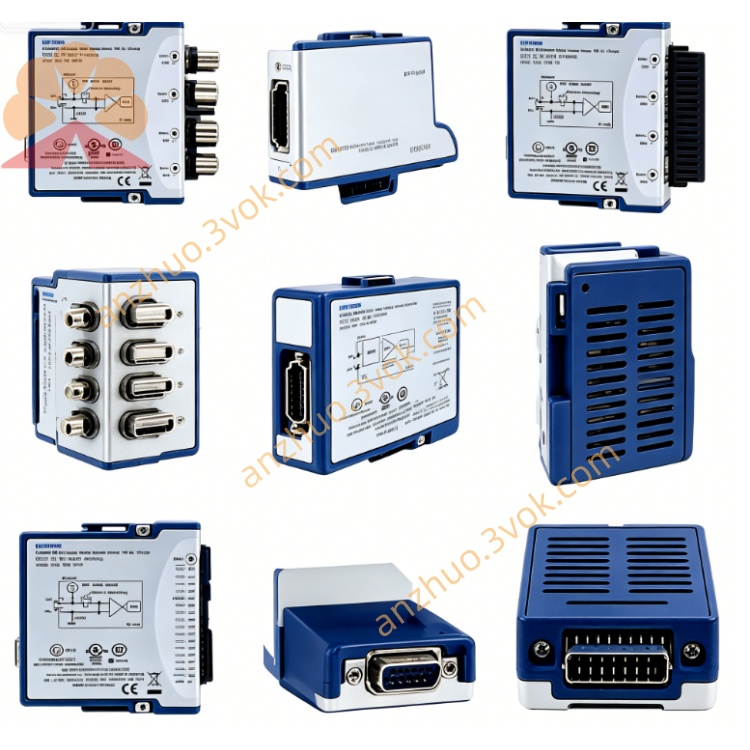
NI PXI‑4472 24‑Bit 8‑Channel Sound‑Vibration DAQ Module
Description
Model Explanation
PXI: Standard 3U PXI bus module, single slot, compatible with PXI/PXIe chassis.
4472: DSA series number, representing 8-channel analog input, 24-bit, IEPE conditioning, dedicated for sound and vibration NI.
Component Number: 779689-01 (only for analog input) NI.
Upgrade Version: PXI-4472B (AC coupling cutoff frequency 0.5 Hz, stronger low-frequency performance).
Technical Parameters (25℃, preheating 15 min)
Channels: 8 differential analog inputs, synchronous sampling NI.
ADC: 24-bit Σ-Δ type.
Sampling Rate: Single channel up to 102.4 kS/s NI.
Dynamic Range: Typical 110 dB.
Input Voltage Range: ±1 V, ±3.16 V, ±10 V, ±31.6 V, ±42.4 V.
Gain: 0 dB, +10 dB, +20 dB, +30 dB (software selectable).
Coupling: Independent AC/DC per channel; AC coupling -3 dB cutoff 3.4 Hz NI.
IEPE Conditioning: Software controllable 4 mA constant current, compliant voltage 24 V.
Input Impedance: Voltage mode 100 kΩ; IEPE mode 10 kΩ.
Anti-aliasing Filter: Built-in programmable, automatically adjusted with sampling rate, no aliasing bandwidth 45 kHz NI.
THD+N: ≤ -95 dB; CMRR (1 kHz) > 60 dB.
Trigger: SMB external trigger, TTL level, rising/falling edge, minimum pulse width 10 ns.
Power Supply: PXI backplane +3.3 V, +5 V, +12 V; maximum power consumption approximately 12 W.
Connectors: 8×BNC (analog input), 1×SMB (trigger) NI.
Size/Weight: 3U single slot (160×100×20 mm), approximately 250 g.
Environment: Operating 0~55℃; Precision guaranteed 15~35℃; Storage -20~70℃.
Calibration: Recommended 1 year, supported by NIST traceability.
Interface and Communication Configuration
Front-end Interface
8×BNC: 8 channels of analog input, supports voltage or IEPE sensor NI.
1×SMB: Trigger input, compatible with PFI/PXI trigger bus.
Panel Indicator Lights
PWR (green): Normal power supply.
RUN (green): Always on = sampling in, flashing = waiting for trigger.
ERR (red): Over temperature, over current or calibration error.
Bus and Synchronization
PXI bus, compatible with PXIe; supports PXI trigger, RTSI synchronization NI.
Multi-module synchronization skew <1 μs.
Software Driver
NI-DAQmx, supports LabVIEW, TestStand, Python, C#.
NI MAX: Device identification, self-check, configuration, calibration.
Companion: Sound and vibration toolkit, order analysis toolkit NI. Core function
8-channel synchronous acquisition: Synchronous delay between channels < 1 μs, suitable for large-scale multi-point synchronous measurement.
High dynamic range: 110 dB, capable of simultaneously acquiring weak and strong amplitude signals.
Integrated IEPE conditioning: 4 mA constant current, directly driving IEPE accelerometers/microphones NI.
24-bit high precision: Low distortion, low noise, suitable for precise dynamic signal measurement.
Independent coupling and filtering: Each channel can be selected for AC/DC, automatic anti-aliasing filtering, interference suppression NI.
TEDS support: Sensor plug-and-play, automatically reads parameters and configures NI.
Multi-module expansion: Multi-module cascading in a single chassis, building a high-density channel system NI. Applicable scenarios
Automobile NVH Testing: Measurement of noise, vibration, and acoustic vibration roughness for the entire vehicle / components (engine, transmission, suspension) NI.
Structural Modal and Health Monitoring: Modal analysis, impact response, resonance detection; monitoring of bridges, buildings, and large equipment NI.
Audio and Acoustic Testing: Array microphone sound field analysis, frequency response and distortion of speakers / headphones, environmental noise monitoring NI.
Industrial Equipment Condition Monitoring: Vibration collection of motors, fans, pumps, bearing / gear fault diagnosis and predictive maintenance NI.
Research and Teaching: Precise measurement in acoustic / vibration laboratories, experiments for related university courses NI.
User and Maintenance Instructions
Installation and Power On
Power off installation, insert single slot and fix; the chassis should be reliably grounded to prevent static electricity.
Preheat for 15 minutes before powering on, NI MAX self-check to confirm no errors.
Ensure normal fan operation of the chassis and unobstructed ventilation ports, with the environment ≤ 55℃.
Cabling and Operation
Use 50 Ω coaxial cable for analog input, shielded single-ended grounding to reduce interference NI.
IEPE sensor channels should be set to 4 mA constant current, and cannot be connected to ordinary voltage signals.
Select AC coupling for AC signals, DC / ultra-low frequency for DC coupling NI.
Set the gain to make the signal reach approximately 80% of the full scale to improve signal-to-noise ratio and avoid overload.
Use PXI trigger or RTSI bus for multi-module synchronization, reducing phase error NI.
Maintenance and Calibration
Perform NIST traceable calibration once a year; enable internal self-calibration to compensate for temperature drift daily.
Regularly clean dust from BNC/SMB interfaces to keep them dry; disconnect power and add a dust cap when the equipment is idle for a long time.
The working environment should be free of condensation, with a humidity of 5% to 95% RH, and away from strong electromagnetic interference equipment.
Do not input > ±50 V voltage; do not plug in or unplug cables while powered on; the IEPE channel should not be connected to electrostatic-sensitive equipment.
Get a Quote