
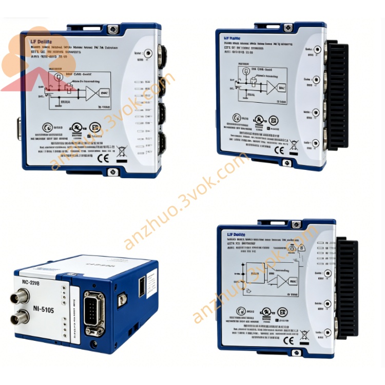
NI PXI‑4472 24‑Bit 8‑Channel Sound‑Vibration DAQ Module
Description
Model Explanation
PXI represents that this product is a standard 3U PXI bus module, with a single-slot structure, and is compatible with both PXI and PXIe hybrid chassis.
4472 belongs to the NI dynamic signal acquisition series number, representing eight analog input channels, 24-bit sampling accuracy, built-in IEPE conditioning function, and is dedicated to audio and vibration signal acquisition.
The standard component number of this product is 779689-01. The module only configures analog input channels and has no analog output channels. This model also has an upgraded version, PXI-4472B, with stronger low-frequency signal acquisition capabilities. Technical Specifications
The test benchmark environment for the equipment is 25 degrees Celsius. Normal operation requires a 15-minute preheating period.
Channel configuration: Eight differential analog input channels, using a 24-bit Σ-Δ analog-to-digital converter. The maximum sampling rate for a single channel is 102.4 kS/s, and the typical dynamic range is 110 dB.
Input voltage range: There are five levels, namely positive and negative 1 volt, positive and negative 3.16 volts, positive and negative 10 volts, positive and negative 31.6 volts, and positive and negative 42.4 volts.
Gain range: Software selectable: 0 dB, +10 dB, +20 dB, +30 dB.
Signal coupling: Each channel supports independent AC coupling and DC coupling. The negative 3 dB cutoff frequency of AC coupling is 3.4 Hz.
IEPE conditioning: Supports software-enabled 4 mA constant current excitation, with a compliant voltage of 24 volts, and can directly drive standard IEPE type sensors.
Input impedance: In voltage mode, it is 100 kΩ; in IEPE working mode, it is 10 kΩ.
Filtering and noise: Built-in automatic anti-aliasing filter, with no aliasing bandwidth of 45 kHz at the highest sampling rate. Total harmonic distortion plus noise does not exceed -95 dB, and the common-mode suppression ratio is greater than 60 dB at 1 kHz operating condition.
Power supply and power consumption: Powered by the PXI backplane, with the maximum power consumption of the entire unit being 12 watts.
Physical specifications: The front end is equipped with eight sets of BNC interfaces and one SMB trigger interface. It has a standard 3U single-slot shape, and the overall weight is approximately 250 grams.
Safety level: Complies with IEC 61010-1 safety standards, with a level of CAT I at 30 volts.
Environmental parameters: Operating temperature range: 0 degrees Celsius to 55 degrees Celsius. The temperature range ensuring measurement accuracy is 15 degrees Celsius to 35 degrees Celsius. The storage temperature range is from -20 degrees Celsius to 70 degrees Celsius.
Calibration requirements: The official recommended calibration cycle is one year, and NIST standard traceable calibration is supported.
Interface and communication configuration
Front-end interface: Eight sets of BNC interfaces correspond to eight analog input channels, capable of connecting to ordinary voltage signals or IEPE sensor signals. One SMB interface serves as a trigger input port, compatible with PFI signals and PXI bus trigger signals, using TTL level, supporting rising edge and falling edge triggering, with a minimum trigger pulse width of 10 nanoseconds.
Panel indicator lights: The power indicator light is always green and indicates normal equipment power supply. The operation indicator light is always green and indicates the module is in a normal acquisition state. The indicator light flashes indicating the module is waiting for a trigger signal. The fault indicator light is red and indicates that the equipment has problems such as over-temperature, over-current, or calibration abnormalities.
Bus and synchronization: Uses the standard PXI bus, compatible with PXIe chassis, supports PXI trigger bus and RTSI synchronous bus. When multiple modules are synchronized working, the channel delay is no more than 1 microsecond.
Driver and software: The accompanying driver program is NI-DAQmx, which can be adapted to mainstream development software such as LabVIEW TestStand, Python, and C#. Through NI MAX software, operations such as device identification, function self-check, parameter configuration, fault排查, and device calibration can be completed. Professional tools include the sound and vibration toolkit, and the frequency analysis toolkit for professional signal analysis and processing. Core function
First, the eight channels are synchronized for collection, and the synchronization delay between channels is less than 1 microsecond, enabling synchronous measurement of signals at multiple points over a wide range.
Second, it has a high dynamic range of 110dB, capable of simultaneously collecting weak signals and large-amplitude signals, and is suitable for various industrial sensors.
Third, it is equipped with an IEPE constant current conditioning circuit, eliminating the need for external signal conditioning equipment, and directly driving IEPE accelerometers and microphones.
Fourth, it has a 24-bit high-precision analog-to-digital conversion, with low overall distortion and low noise, meeting the precise measurement requirements of audio vibration acoustics.
Fifth, each channel supports independent AC/DC coupling and automatic anti-aliasing filter, effectively filtering out interference signals from the site, and is suitable for various types of measured signals.
Sixth, it supports the TEDS sensor automatic identification function, which can read the built-in parameters of the sensor, automatically complete sensitivity setting and parameter calibration.
Seventh, it supports multi-module synchronous expansion, with multiple blocks of the same model modules integrated in a single chassis, enabling rapid construction of large-scale high-density acquisition systems. Applicable scenarios
1. Noise and vibration testing for the automotive industry, for multi-channel noise and vibration detection of complete vehicles and various components, applicable for synchronous state monitoring of engine, transmission, suspension and other components.
2. Structural testing and equipment health monitoring, conducting multi-channel modal analysis, impact response testing, resonance point detection, applicable for long-term state monitoring of bridges, buildings and large mechanical equipment.
3. Audio and acoustic testing, setting up a multi-microphone array to complete sound field analysis, conducting audio product parameter testing, also applicable for multi-point environmental noise monitoring.
4. Industrial rotating equipment monitoring, collecting vibration data from multiple measurement points for motors, fans, pumps and other equipment, completing bearing and gear fault diagnosis and predictive maintenance of equipment.
5. Research and teaching fields, used for precise experimental measurement in acoustic vibration-related laboratories and teaching experiments for dynamic signal analysis in universities.
Installation and Power On
Before installing the module, it is necessary to turn off the total power of the PXI chassis. Insert the module smoothly into the single slot of the chassis and tighten the fixing screws. Ensure the chassis is reliably grounded to avoid damage to the module hardware due to static electricity.
After powering on the equipment, preheat for 15 minutes to ensure measurement accuracy. Open the NI MAX software to check the equipment status and confirm that the self-check results are normal.
During operation, ensure that the fan of the chassis is working normally, the ventilation ports of the module are kept unobstructed, and the working temperature of the environment does not exceed 55 degrees Celsius.
Connection and Operation
Use 50-ohm coaxial cables to connect the analog input channels. The shield layer of the cable adopts single-ended grounding to reduce external electromagnetic interference.
When using IEPE sensors, open the 4-milliamp constant current output for the corresponding channel. This channel cannot be connected to ordinary voltage signals.
Select AC coupling mode for collecting audio vibration type AC signals, and DC coupling mode for collecting DC or ultra-low frequency signals.
Reasonably set the channel gain to make the input signal amplitude reach about 80% of the full scale, improve the signal-to-noise ratio, and avoid signal overload.
During multi-module synchronous collection operations, uniformly use the PXI trigger bus or RTSI bus to ensure all modules are time-synchronized and reduce phase errors.
Maintenance and Calibration
Complete external traceability calibration work on a one-year cycle. During daily use, enable the internal self-calibration function of the equipment to compensate for measurement errors caused by temperature changes.
Regularly use a dry soft cloth to clean the dust on the BNC and SMB interface surfaces to keep the interfaces dry and clean. When the equipment is idle for a long time, disconnect the power supply, install a dust cap on the interface to prevent metal terminals from oxidizing.
Maintain the equipment environment without condensation, control the relative humidity of the air between 5% and 95%, and keep away from strong electromagnetic interference equipment such as large-power motors and frequency converters.
Use the equipment strictly in accordance with the specifications. Do not connect voltage signals exceeding ±50 volts. Do not plug or unplug the connection cables while the equipment is powered on. The IEPE function channel is prohibited from connecting electrostatic-sensitive components to prevent electrostatic breakdown from causing hardware damage.
Get a Quote