
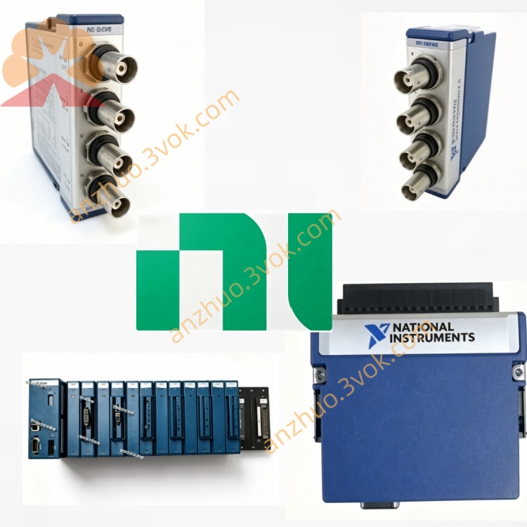
NI PXI‑4462 4‑Channel 24‑Bit Sound‑Vibration DSA Module
Description
Model Explanation
PXI represents the standard 3U PXI bus module, with a single-slot structure, compatible with both PXI and PXIe hybrid chassis.
4462 belongs to the NI Dynamic Signal Acquisition series, representing four-channel analog input, 24-bit resolution, high dynamic range, and integrated IEPE conditioning function, targeting audio vibration type tests.
779688-01 is the standard part number of this product. The module is only equipped with analog input channels and has no analog output channels. Technical Specifications
The test benchmark environment is at 25 degrees Celsius, and the equipment is preheated for 30 minutes.
Channel configuration: There are a total of four analog input channels, using differential and pseudo-differential input modes, equipped with a 24-bit Σ-Δ type analog-to-digital converter. The single-channel maximum sampling rate is 204.8 kS/s, and the typical dynamic range is 118 dB.
The input voltage ranges are six levels, namely positive and negative 316 mV, positive and negative 1 V, positive and negative 3.16 V, positive and negative 10 V, positive and negative 31.6 V, and positive and negative 42.4 V.
The software offers selectable gain levels including -20 dB, -10 dB, 0 dB, +10 dB, +20 dB, and +30 dB.
Each channel supports independent AC coupling and DC coupling switching.
Integrated IEPE sensor conditioning circuit, output constant current divided into 0 mA, 4 mA, and 10 mA, with a compliance voltage of 24 V, capable of directly driving IEPE accelerometers and microphones.
In voltage mode, the input impedance is 100 kΩ, and in IEPE mode, the input impedance is 10 kΩ.
The highest sampling rate's no aliasing bandwidth is 92 kHz, the total harmonic distortion plus noise index is no higher than -100 dB, and the common mode rejection ratio is greater than 100 dB at 50 Hz and 60 Hz.
Electrical mechanical parameters: Powered by the PXI backplane, the maximum power consumption of the entire machine is 10 watts.
The front end is equipped with four BNC interfaces and one SMB trigger interface, with a standard 3U single-slot shape, and the total weight of the machine is approximately 240 grams.
The safety level complies with IEC 61010-1 standard, CAT I 30 V.
The operating temperature range is 0 degrees Celsius to 55 degrees Celsius, and the temperature range ensuring measurement accuracy is 15 degrees Celsius to 35 degrees Celsius. The storage temperature range is from -20 degrees Celsius to 70 degrees Celsius.
The official recommended calibration cycle is one year, and NIST traceable calibration is supported.
Interface and communication configuration
Front-end interface: Four BNC interfaces correspond to four analog input channels, supporting voltage signals and IEPE sensor signals input.
One SMB interface serves as a trigger input interface, supporting PFI and PXI bus trigger signals, using TTL level, selectable rising edge or falling edge triggering, with a minimum trigger pulse width of 10 nanoseconds.
Panel indicator lights: The power indicator light is always on green, indicating normal power supply. The operation indicator light is always on green, indicating normal data acquisition by the equipment, and the indicator light flashes indicating the device is in trigger waiting state. The fault indicator light is red, indicating faults such as overheating, overcurrent, or calibration abnormalities in the equipment.
Bus and software: Using standard PXI bus, compatible with PXIe chassis, supporting PXI trigger bus and PFI signals, multi-module synchronization delay does not exceed 1 microsecond.
The accompanying driver is NI-DAQmx, which can be used in development environments such as LabVIEW TestStand Python C#.
The device identification, self-check, parameter configuration, fault detection and calibration operations are completed through NI MAX software.
The professional tool package includes the sound and vibration tool package, and the order analysis tool package. Core function
First, the four channels are synchronized for data collection, and the multi-channel synchronization delay is less than 1 microsecond, meeting the requirements for synchronous signal collection at multiple points.
Second, it has an ultra-high dynamic range of 118dB, capable of simultaneously collecting weak signals and large-amplitude signals, and is suitable for various sensors such as microphones and accelerometers.
Third, it has an internal IEPE constant current conditioning circuit, without the need for external conditioning equipment, and can directly drive mainstream IEPE-type sensors.
Fourth, it has a 24-bit high-precision conversion circuit, with excellent distortion indicators, suitable for various precise dynamic signal measurements.
Fifth, each channel is equipped with an independent programmable anti-aliasing filter, combined with AC/DC coupling functions, effectively suppressing on-site noise, and suitable for different types of input signals.
Sixth, it supports TEDS sensor automatic identification, can read the built-in parameters of the sensor, and automatically complete sensitivity and calibration configuration.
Seventh, it supports multi-module synchronous expansion, with a maximum of 17 blocks of the same model modules that can be integrated in a single chassis, building a large-scale multi-channel acquisition system. Applicable scenarios
1. Noise and vibration testing for the automotive industry, used for multi-point noise and vibration monitoring of complete vehicles and components, suitable for synchronous detection of engine, transmission, suspension and other components.
2. Structural mechanics testing, conducting multi-channel modal analysis, impact response testing, resonance point detection, applied to bridge construction and the health monitoring of large industrial equipment.
3. Audio-related testing, setting up a multi-microphone array to complete sound field analysis, conducting multi-channel parameter tests for audio products such as speakers and headphones.
4. Industrial equipment condition monitoring, collecting multi-point vibration data for rotating equipment such as motors, fans and water pumps, achieving bearing and gear fault diagnosis and predictive maintenance of equipment.
5. Acoustic environment testing, completing multi-point environmental noise monitoring, conducting tests on the sound insulation and sound absorption performance of building materials.
6. Research and teaching fields, used for laboratory acoustic vibration-related experimental measurements, as well as teaching dynamic signal analysis courses in universities.
Installation and Power On
Before installing the module, it is necessary to turn off the total power of the PXI chassis. Insert the module smoothly into the single slot and tighten the fixing screws to ensure reliable grounding of the chassis to prevent damage to hardware due to static electricity.
After powering on the equipment, let it preheat for 30 minutes to ensure measurement accuracy. Start the NI MAX software to check the equipment status and confirm that there are no errors during self-check.
During use, ensure that the fan of the chassis is running normally, the ventilation ports of the equipment are not blocked, and the working environment temperature does not exceed 55 degrees Celsius.
Wiring and Operation
The analog input channels use 50-ohm coaxial cables for connection. The shield layer of the cable adopts single-ended grounding to reduce electromagnetic interference.
When using IEPE sensors, the corresponding channel should be enabled for constant current output. This channel should not be connected to ordinary voltage signals.
Select AC coupling for collecting audio-vibration type AC signals, and DC coupling or ultra-low frequency signals for collecting DC or ultra-low frequency signals.
Reasonably set the channel gain to make the input signal amplitude reach about 80% of the full scale, improving the signal-to-noise ratio and avoiding signal overload.
When collecting data from multiple modules synchronously, use the PXI trigger signal uniformly to ensure time synchronization of each module and reduce phase errors.
Maintenance and Calibration
Complete external traceability calibration once a year. Use the internal self-calibration function of the equipment for daily use to compensate for measurement errors caused by temperature.
Regularly use a dry soft cloth to clean the dust on the BNC and SMB interface surfaces to keep the interfaces dry and clean. Disconnect the power supply when the equipment is idle for a long time, install dust caps on the interfaces to prevent metal terminals from oxidizing.
Maintain the equipment operating environment without condensation. Control the relative humidity of the air between 5% and 95%. Keep away from strong electromagnetic interference equipment such as high-power motor frequency converters.
Strictly follow the rated voltage range for use. Do not connect voltage signals exceeding ±50 volts. Do not plug or unplug interface cables while the equipment is powered on. The IEPE channel should not be connected to electrostatic-sensitive components to avoid electrostatic breakdown and damage to the components.
Get a Quote