
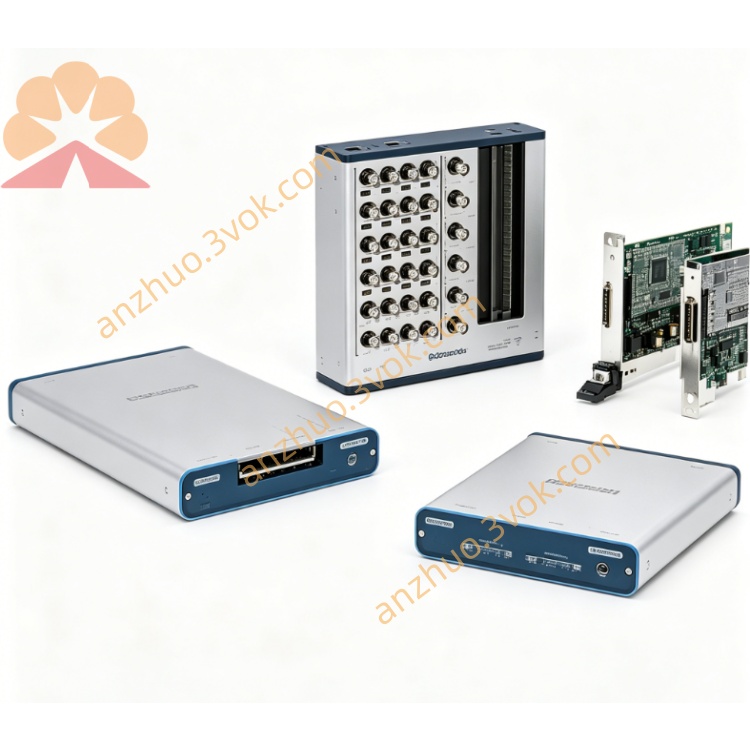
NI PXI‑2576 64‑Channel 2‑Wire PXI Multiplexer Switch Module
Description
II. Model Interpretation
PXI: Standard PXI bus, compatible with PXIe mixed slots.
2576: NI multi-group multiplexer series code, representing 16 groups of 4×1 dual-line multiplexers (expandable to 64 channels).
Full name: PXI-2576 64-channel dual-line multi-group PXI multiplexer module.
Topology identification: Supports 5 fixed topologies (software configuration):
16 groups of 4×1 dual-line (independent parallel)
8 groups of 8×1 dual-line
4 groups of 16×1 dual-line
2 groups of 32×1 dual-line
1 group of 64×1 dual-line NI
III. Technical Parameters
(1) Switch and Electrical Characteristics
Topology: 16 groups of 4×1 dual-line (default), reconfigurable to 8/4/2/1 groups, maximum 64×1 dual-line multiplexer NI.
Relay type: Electromechanical latch relay, gold-plated contacts, pulse drive (only switching power consumption).
Maximum switching voltage: 100 VDC / 100 Vrms (CAT I), pulse withstand voltage 500 VNI.
Single-channel maximum switching/carrying current: 1 A (resistive load) NI.
Maximum switching power: DC 30 W, AC 37.5 VA.
On-resistance: Typical value 0.5 Ω, initial < 1.1 Ω, end of life ≥ 2 Ω.
Thermal offset: Typical value **< 10 µV**.
Working bandwidth (50 Ω system) NI:
4×1/8×1: > 60 MHz
16×1: > 40 MHz
32×1: > 20 MHz
64×1: > 10 MHz
Action time: Typical 2 ms, maximum 3.4 ms.
Channel isolation: 10 kHz > 90 dB; 100 kHz > 70 dB; 1 MHz > 50 dB.
Minimum load: 20 mV / 1 mA.
(2) Life and Scan Parameters
Mechanical life: 2×10⁷ on/off cycles.
Full-load electrical life: 1×10⁵ on/off cycles.
Scan list: Maximum 32,000 programmable scan sequences.
Full-channel scan rate: Maximum 130 times/second NI.
(3) Trigger and Control
Trigger channels: Supports PXI backplane Trigger 0~Trigger 7 hardware trigger bus.
Minimum trigger pulse width: 150 ns (disable digital filtering).
Built-in functions: Each relay has an independent counter, and the locked state is maintained during power failure.
(4) Physical and Environmental Parameters
Form specification: Standard 3U PXI single-slot module.
Front-end connector: 200-pin LFH matrix male connector.
Form size: 216 mm × 20 mm × 130 mm.
Weight: Approximately 0.3 kg.
Power supply: PXI backplane 3.3 V/5 V; typical power consumption 2.5 W (3.3 V) + 10 W (5 V); latch stable zero power consumption.
Operating temperature: 0 ℃ ~ 55 ℃.
Storage temperature: -20 ℃ ~ 70 ℃.
Relative humidity: 5% ~ 85%, no condensation.
IV. Interfaces and Topology Configuration
Front-end I/O interface
All signals are led out through 200-pin LFH matrix male connector, including:
16 groups of 4×1: 16 differential common terminals + 64 differential inputs;
64×1: 1 differential common terminal (COM+、COM‑) + 64 differential inputs (CH0+~CH63+、CH0‑~CH63‑);
The remaining pins are shielding ground and reference ground, with electrical isolation between channels NI. Bus and Software Communication
Bus Interface: Standard PXI backplane, compatible with PXIe mixed slots, automatically acquires power, clock, and trigger NI.
Driver: Standard NI- SWITCH, compliant with IVI specifications NI.
Software Support: LabVIEW, TestStand, LabWindows/CVI, Python, etc.
Basic Functions: NI MAX can perform hardware recognition, topology configuration, channel status reading, scan editing, trigger configuration, and lifetime count query.
Synchronization Capability: PXI trigger bus enables multi-module high-precision synchronous switching.
VII. Core Functions
Flexible Reconfigurable Topology: Single module supports 5 types of channel configurations, balancing parallel multi-group measurement and high-channel-count centralized routing, without the need to replace hardware.
Latched Low-Power Design: Only power consumption during switching, zero power consumption in steady state, suitable for long-term operation, battery-powered systems.
Medium and High Frequency Signal Routing: Up to 60 MHz bandwidth (4×1 mode), suitable for differential high-frequency analog and digital signal switching.
High-Speed Hardware Scan: 32,000-step scan list, executed by hardware automatically, improving high-channel-count test throughput.
Hardware Synchronous Trigger: PXI backplane trigger, precise timing, meeting requirements for multi-instrument collaboration and parallel testing.
Relay Lifespan Monitoring: On-board counter records on/off times, supporting predictive maintenance, reducing downtime.
Power Failure State Retention: Locks relay power-off to maintain channel status, no need for reconfiguration upon restart, enhancing system stability.
VIII. Application Scenarios
Semiconductor Testing: Parallel inspection or centralized multiplexing of multi-pin differential signals for wafers/chips.
Automotive Electronics: Differential signal switching for ECU, wiring test, sensor signal parallel acquisition.
Industrial Data Acquisition: Multi-channel differential sensor (voltage/current/resistance) signal multiplexing.
ATE Equipment: High-channel-count function testing, aging testing, differential signal routing matrix.
Laboratory Research: Comparative testing of multi-channel differential signals, loop switching, high-frequency signal routing verification.
Parallel Test System: Synchronous measurement at multiple stations, each group independently 4×1 multiplexing, enhancing test efficiency.
IX. Usage and Maintenance Instructions
Usage Points
Installation: Insert into 3U standard slot, tighten panel screws, keep away from strong vibration / strong electromagnetic interference; PXIe chassis prioritizes mixed slots NI.
Connection: Match 200-pin LFH cable, gently insert and remove; use shielded twisted pair for high-frequency / precise differential signals and reliable grounding.
Electrical Limits: Strictly follow 100 V/1 A rated parameters; external connect diodes for inductive loads to prevent reverse high voltage from damaging contacts.
Topology Selection: 16 groups of 4×1 for parallel measurement; 64×1 for high-channel-count centralized routing, software one-click switch.
Trigger Mode: Software trigger for debugging; PXI hardware trigger for high-speed / multi-module synchronization.
Maintenance Instructions
Regular Inspection: Check 200-pin LFH connector quarterly, clean dust, and check for loose oxidation.
Lifespan Management: Regularly read on/off times, plan to replace relays in advance when the load condition approaches 1×10⁵ times (support on-site single-path replacement).
Environmental Control: Maintain dry and ventilated, temperature 0~55 ℃, avoid condensation and dust accumulation.
Fault Handling: First check wiring, grounding, and topology configuration for channel abnormalities; single-path faults can be replaced on-site with relays.
Storage Requirements: Disconnect cables when not in use, protect interface from dust, store in a dry environment at -20~70 ℃.
Calibration: Suggested annual calibration, test on/off status, conduction resistance, bandwidth, and latch retention performance.
Get a Quote