
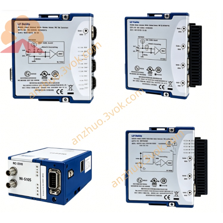
NI PXI‑2566 16‑Channel 2‑A SPDT PXI Relay Module
Description
Model Explanation
PXI: PXI Bus Standard (PCI eXtensions for Instrumentation)
2566: NI series model number, defined as 16-channel SPDT, 2 A, low-noise universal relay module
Full Name: PXI-2566 → 16-Channel, 2 A, SPDT PXI Relay Module
Topology Alias: NISWITCH_TOPOLOGY_2566_16_SPDT (default); Can be cut 8×DPDT download.ni.com Technical Specifications
Switch and Electrical Characteristics
Topology: 16 independent SPDT (Form C, COM/NO/NC); software configurable for 8 DPDT download.ni.com
Relay: Electromechanical, non-latching, gold-plated contacts, low thermal offset NI
Maximum switching voltage: 150 VDC / 125 VAC (CAT I); can withstand 800 V pulse
Maximum switching current: 2 A (DC/AC); carries current 5 A (DC/AC) NI
Maximum switching power: 60 W (DC) / 62.5 VA (AC, DC–60 Hz) NI
On-state resistance (typical): <50 mΩ
Thermal offset (typical): <1 µV
Bandwidth: DC~10 MHz
Action time: typical 2 ms, maximum 4.4 ms
Scan rate: maximum 115 times/second (full channel)
Relay lifespan:
Mechanical: 2×10⁷ times
Full-load electrical: 1×10⁵ times (2 A)
Isolation withstand voltage: channel-to-channel / channel-to-ground 150 Vrms NI
Trigger and Control
Trigger: PXI Trigger 0–7, hardware synchronization
Scan list: maximum 1024 steps, deterministic scan
Relay count: onboard closed count, health monitoring NI
Physical and Environmental
Form: PXI 3U single slot
Connector: front panel 62-pin D-SUB (male)
Size: approximately 216×20×130 mm
Weight: approximately 0.25 kg
Temperature: operating 0–55°C; storage –20–70°C NI
Power consumption: 5 V approximately 4.5 W; 3.3 V approximately 2.5 W
Interface and Communication Configuration
Front panel I/O (62-pin D-SUB male connector)
16×SPDT mode: each COM/NO/NC, total 16×3=48 pins; the rest are ground / shielding
8×DPDT mode: each double NO / double NC/COM, total 8×5=40 pins
Backplane and Driver
Bus: PXI Hybrid Slot (compatible with PXI-1/PXIe)
Driver: NI-SWITCH (IVI), supports LabVIEW, TestStand, Python, etc.
Software Features: MAX identification, topology switching, trigger management, relay life tracking NI
Core Functions
16×SPDT / 8×DPDT Reconfigurable: Single module can meet single-pole-double-throw or double-pole-double-throw requirements
Low noise + low thermal offset: <1 µV thermal offset, suitable for precise voltage/current measurement
Medium to small power switching: 2 A / 150 V, balancing signal integrity and power capacity
Hardware Trigger Synchronization: Sequential synchronization of multiple modules < 1 µs, suitable for high-speed ATE
Relay Health Monitoring: On-board counting, predictive maintenance, reducing downtime risk
High Channel Density: 16 SPDT per slot in a single slot, saving chassis slots Applicable scenarios
Precision ATE Testing: Signal routing and power switching of semiconductors, components, and circuit boards
Automotive Electronics: Sensor signal switching, ECU low-power load control, wiring harness testing
Industrial Control: PLC signal conversion, relay simulation, low-voltage circuit control
Data Acquisition: Multi-channel signal selection, sensor multiplexing, low-level signal switching
General Testing: Requires SPDT/DPDT switching, low noise, medium power automated system
User Manual and Maintenance Instructions
Installation and Configuration
Insert the PXI 3U single slot and fix it.
Install NI-SWITCH, and the MAX will identify and select the topology (16×SPDT/8×DPDT).
Connect the 62-pin D-SUB cable. Shielded lines for high-power circuits and reliable grounding are used.
Operation Points
Power Limit: No more than 2 A / 150 V; Inductive loads (winding / motor) must have shunt protection from NI.
Trigger Selection: Software trigger for debugging; PXI hardware trigger for high-speed synchronization.
Channel Control: 16 independent on-off channels, not interfering with each other.
Maintenance Calibration
Life Monitoring: The number of NI-SWITCH reads, approaching 1×10⁵ times (full load) triggers replacement.
Regular Inspection: Check D-SUB connections, oxidation, and looseness every quarter; Clean contacts.
Environment: 0–55°C, humidity 5%–85% (no condensation) from NI.
Replacement: Non-user-replaceable relays. Faults require return to factory or module replacement.
Get a Quote