
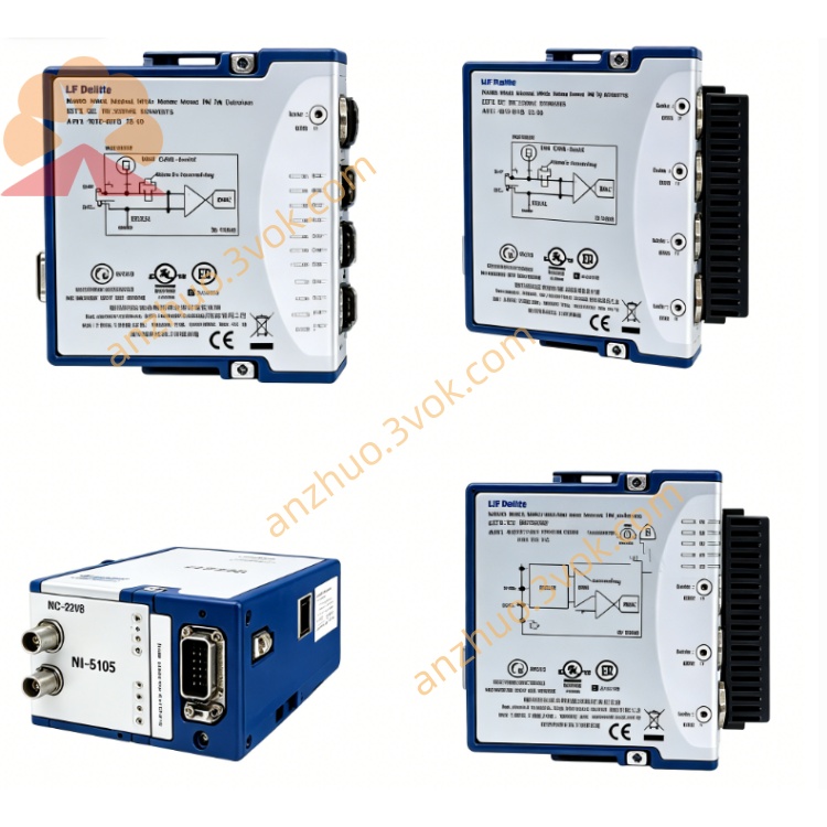
NI PXI‑2545 2.7‑GHz 50‑Ohm Terminated SP4T RF Multiplexer Module
Description
II. Model Interpretation
PXI: PXI Hybrid Bus (compatible with PXIe Hybrid Slot) NI
2545: Serial Number, representing 2.7 GHz, single 4×1, with termination, electromechanical RF multiplexer
Alias: NI-2545, 4x1 Terminated Mux, SP4T RF Switch NI
Position: Single group 4-out-of-1 RF switch, electromechanical relay + full-channel termination, balancing cost and performance
III. Technical Specifications
Basic Specifications
Topology: Single 4×1 (SP4T), CH0~CH3 → COM NI
Relay Type: Electromechanical Relay (EMR) NI
Frequency Range: DC~2.7 GHz (‑3 dB) NI
Characteristic Impedance: 50 Ω NI
Termination: Built-in 50 Ω termination for all input channels (automatically connected when not selected) NI
RF Performance (Typical)
Insertion Loss:
1 GHz: <0.7 dB
2.7 GHz: <1.7 dB
Isolation:
1 GHz: >50 dB
2.7 GHz: >40 dB
VSWR: <1.3 (within 2.7 GHz)
Maximum Switching Power: +24 dBm (continuous)
Terminal Power: 1.5 W @25 °C (temperature rating reduced at high temperatures) NI
Electrical and Dynamic
Maximum Switching Voltage: 30 VAC / 42 VDC NI
Maximum Switching Current: 0.5 A
Switching Time: Typical 5 ms (electromechanical)
Relay Life: 1,000,000 times (typical), board-mounted counter tracking NI
Physical and Environment
Connector: 5×SMA Female (CH0~CH3, COM) NI
Size: 3U PXI Single Slot
Power Consumption: 12 V ≈ 0.35 W
Operating Temperature: 0~55 °C
Storage Temperature: -40~70 °C
IV. Interface and Communication Configuration
Front-end Interface
RF Interface: 5×SMA Female
CH0, CH1, CH2, CH3: 4 RF Input Channels
COM: Common Output NI
Trigger Interface: No independent trigger (software / backplane trigger control)
Bus and Control
Bus: PXI Hybrid Bus (compatible with PXIe Hybrid Slot) NI
Driver Software: NI-SWITCH, MAX, LabVIEW, TestStand, Switch Executive
Programming API: niSwitch Connect/Disconnect, IVI Driver NI
Configuration Method: Software to set channel mapping, scan sequence, relay counter reading NI
V. Core Functions
Single 4×1 RF Routing: 4-out-of-1 signal switching, simplifying multi-DUT test wiring NI.
Full-channel 50 Ω Termination: Unselected channels automatically connect to load to prevent signal source burnout and improve system stability NI.
2.7 GHz Broadband Coverage: Covers mainstream mid-low frequency radio frequency bands such as Bluetooth, WiFi, ISM, 2G/3G NI.
Electromechanical Relay Low Loss: Compared to solid-state, lower insertion loss and lower cost, suitable for scenarios sensitive to loss.
Relay Counting: Board-mounted counter, real-time statistics of switching times, predicting lifespan and reducing downtime NI.
PXI Standard Integration: Single-slot 3U size, seamlessly integrated with PXI chassis, compatible with automated test systems.
VI. Application Scenarios
Consumer Electronics RF Testing: Bluetooth, WiFi, 2G/3G, NFC module functions and mass production testing NI. Multi-channel RF signal switching: Expansion of signal source / spectrum analyzer / network analyzer channels, multi-DUT polling test.
Mass production ATE testing: Cost-sensitive, medium-low frequency, medium switching times mass production line NI.
Research and development laboratory: RF signal routing, instrument interconnection, solution verification, balancing performance and budget.
Semiconductor RF chip testing: Functional verification, parameter testing, aging screening of medium-low frequency RF ICs.
VII. Usage and Maintenance Instructions
Usage Points
Installation: Standard 3U PXI single slot, lock the panel, ensure good contact of the backplane; avoid strong vibration.
Connection: SMA should be inserted and removed gently, no violence is allowed; RF power ≤ +24 dBm, avoid over-power damage.
Power-on state: By default, all channels are disconnected from COM, unselected channels are automatically connected to 50 Ω terminals NI.
Software Control: Use NI-SWITCH or LabVIEW VI for Connect/Disconnect; read the relay count NI.
Environment: 0 - 55 °C, dust-proof and moisture-proof; away from strong electromagnetic interference, ensure good grounding.
Maintenance Instructions
Regular Inspection: Check SMA connectors for looseness and oxidation every quarter; clean the panel and ventilation ports.
Life Management: Electromechanical relays approximately 1 million times; regularly read the onboard count, plan for replacement in advance NI.
Troubleshooting: First check SMA connection and grounding for abnormal signals; use MAX to diagnose switch status; take precautions against static electricity.
Storage: Power off for long periods, cover SMA with a dust cap, store dry and dust-free, avoid high temperature and high humidity.
Calibration: Suggest calibrating once a year to ensure insertion loss, isolation, and VSWR meet specifications.
Get a Quote